Applicator of microwave plasma generator and microwave plasma generator including this applicator

a microwave plasma generator and microwave plasma technology, applied in the field of microwave plasma generators and microwave plasma generators including this applicator, can solve the problems of increasing the size, complexity and price of the known microwave plasma generators, reflected power, and relatively complicated and expensive problems, and achieves the effects of simple, compact, and easy transportation

Inactive Publication Date: 2010-12-02
SPATENKA PETR
View PDF17 Cites 0 Cited by
  • Summary
  • Abstract
  • Description
  • Claims
  • Application Information

AI Technical Summary

Benefits of technology

[0015]The advantage of the above described applicator and microwave plasma generator including this present applicator consists in the fact that it is possible to exclude from construction of the device the expensive and bulky circulator including wave-guide and the tunable short connection of the microwave guide and that it is possible to create a simple, compact, easily transportable microwave plasma generator with a small size and low production costs.

Problems solved by technology

One of the general problems in transmission of electro-magnetic field to plasma is the fact that a certain part of the supplied power is reflected back.
This problem is significant especially in microwave generators since the reflected waves are transmitted via the wave-guide back to the source (magnetron).
A long time charging of the magnetron by the reflected wave can result in the destruction thereof.
Even though the circulator is an efficient device, it is relatively complicated and expensive.
It increases considerably the size, complexity and price of the known microwave plasma generators.
Then the waves from the opposite outputs meet in the guiding part in the place of the input of the microwave power source (magnetron) with exactly the opposite polarity, which disturbs their impact resulting in liberating the magnetron from the impact of reflected waves.

Method used


Image

  • Applicator of microwave plasma generator and microwave plasma generator including this applicator
  • Applicator of microwave plasma generator and microwave plasma generator including this applicator
  • Applicator of microwave plasma generator and microwave plasma generator including this applicator

Examples


Embodiment Construction

OF PREFERRED EMBODIMENTS

[0019]It should be understood that the hereinafter described and shown specific examples of embodiments of the invention are represented as examples only, not as a limitation of the invention. Those skilled in the art will find or will be able to find by routine experimenting a greater or smaller number of equivalents of the present invention, described here in a specific embodiment. Also these equivalents shall be included in the claims for protection.

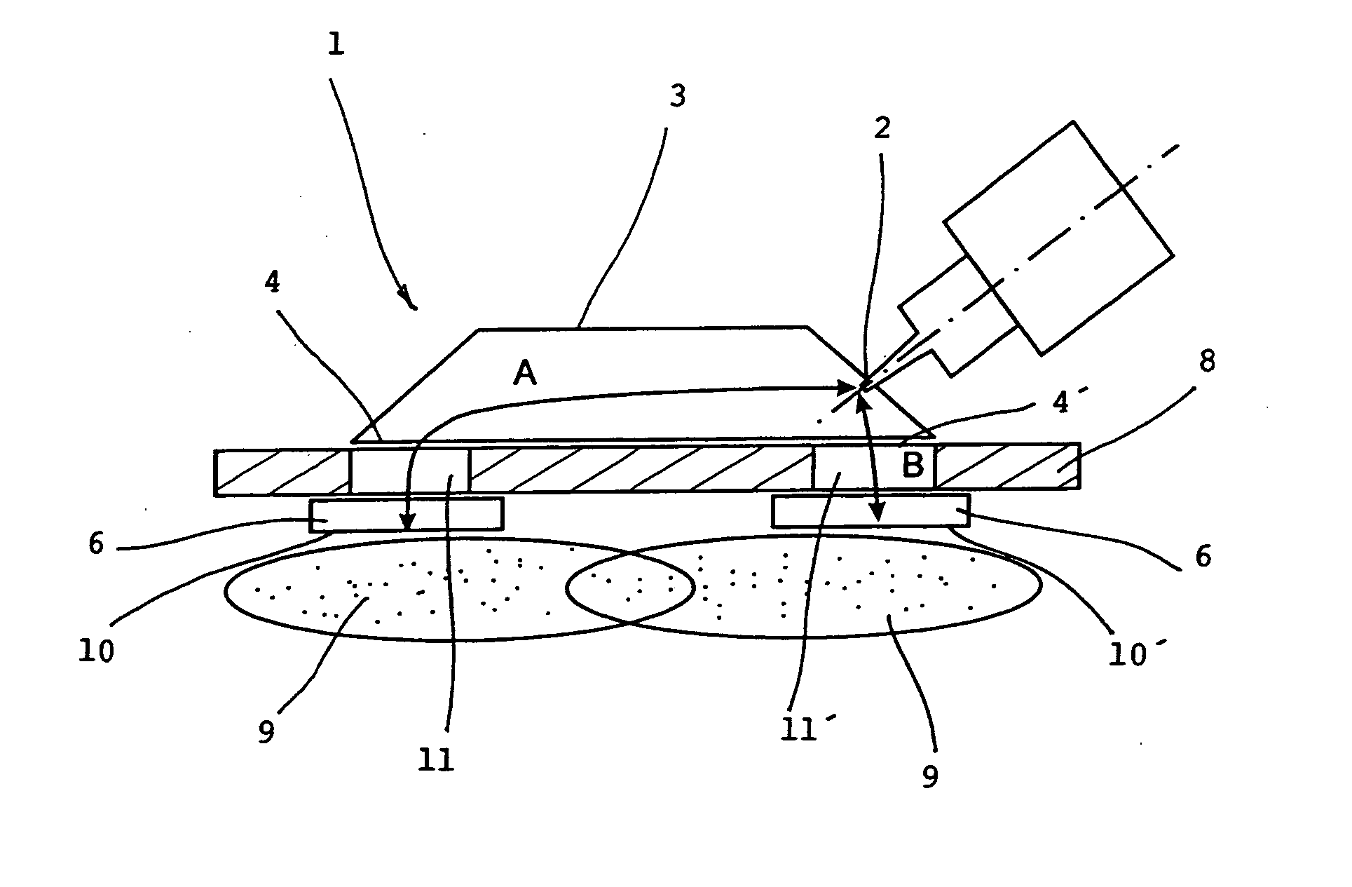
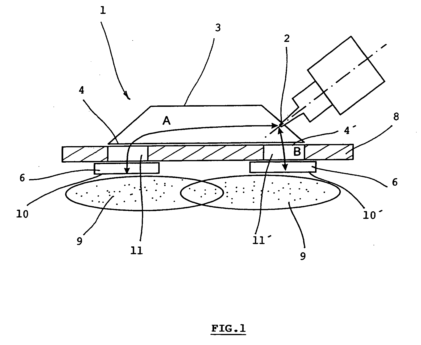
[0020]In one specific embodiment of the invention shown schematically in FIG. 1 there is shown an open microwave plasma generator supplied from a source of pulse voltage 3 kV not presented here adapted for plasma modification of powder materials on the polyethylene basis.

[0021]The microwave power source (magnetron) 5 is a Panasonic magnetron having 1 kW power with a pulse control of power, set in the wall of the guiding part 3 of the applicator 1 made of brass sheet. The guiding part 3 is of a hollow body shape...


PUM


Abstract

The microwave plasma generator is applied to transmission of electromagnetic field into plasma. The invention consists of the fact that the guiding part (3) has two outputs (4, 4′) between which an input (2) of microwave is placed generated from the microwave power source (5). The input (2) is in the distance (A) from the separation (10) of the first output (4) and in the distance (B) from the separation (10′) of the second output (4′) while the absolute value of the difference of the distances A-B or B-A equals λ/2 where λ is the wave length of the microwave and distances A and B correspond to the trajectory of microwave propagation. A microwave plasma generator including microwave power source (magnetron) (5) is connected to the input (2) of the guiding part (3) of the applicator (1)

Description

BACKGROUND AND SUMMARY OF THE INVENTION[0001]The invention relates to an applicator of microwave plasma generator applied to transmission of electromagnetic field into plasma and it further relates to a microwave plasma generator including the dealt with applicator.[0002]A large scale of types of microwave plasma generators that can be, in general, characterized as closed generators where the plasma chamber is surrounded by metal walls forming a microwave resonator, or as open generators including among others microwave emitters, slow-wave structures and surfatrons, eventually generators with magnetic field based on electron resonance ECR (electron cyclotron resonance).[0003]The known microwave plasma generator consists from a microwave power source (magnetron), wave-guide, circulator and from an applicator ensuring transfer of microwave energy into plasma filler (plasma bulk).[0004]The Horn antenna is most frequently used in current microwave plasma generators as applicator, which ...

Claims


Application Information

Patent Timeline
Patent Type & Authority Applications(United States)
IPC IPC(8): H05H1/46
CPCH05H1/46H01J37/32192
Inventor SPATENKA, PETR
Owner SPATENKA PETR
Why Eureka
Try Eureka