A large-area quartz wafer grinding device and grinding method thereof

A technology for quartz wafers and grinding methods, which is applied in the direction of grinding devices, grinding machine tools, and parts of grinding machine tools, and can solve problems such as damage to thin substrates, increased resistance, and unsuitable processing of thin quartz crystal substrates.

Active Publication Date: 2022-03-18
TANGSHAN GUOXIN JINGYUAN ELECTRONICS CO LTD
View PDF4 Cites 2 Cited by
  • Summary
  • Abstract
  • Description
  • Claims
  • Application Information

AI Technical Summary

Problems solved by technology

Double-sided grinding with fixed abrasives is an effective processing method that takes into account both high surface quality and high surface shape accuracy. It can improve the bonding error of paraffin during processing and the deformation caused by the stress difference between the two surfaces of the processed substrate. However, large-area quartz crystals The thin substrate has a large diameter-to-thickness ratio and a thinner thickness. During double-sided grinding, the close contact between the large-area quartz crystal thin substrate and the grinding disc will increase the resistance during processing, resulting in damage to the thin substrate.
Therefore, double-sided grinding is mainly suitable for ultra-precision processing of thicker substrates, and is not suitable for processing thin quartz crystal substrates.

Method used


Image

  • A large-area quartz wafer grinding device and grinding method thereof
  • A large-area quartz wafer grinding device and grinding method thereof
  • A large-area quartz wafer grinding device and grinding method thereof

Examples


Embodiment Construction

[0039] The present invention will be further described below in conjunction with the accompanying drawings and specific embodiments.

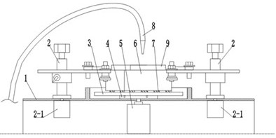
[0040] See Figure 1, figure 2 , image 3 , Figure 4 , the large-area quartz wafer grinding device of the present invention is provided with a base 1, a support arm assembly 2, a grinding disc 3, a rotating seat 4, a rotating motor 5, a loading block 9, a repairing ring 6 and a dropper; The pedestal 1 is a square pedestal arranged on a horizontal plane, and support arm assemblies 2 are installed at both ends of the diagonal line of the pedestal 1, and a drop feeder is arranged on the platform behind the base 1; the drop feeder The discharge port of drip tube 8 is located above the central position of grinding disc 3; 4 is provided with three sets of positioning holes matched with positioning pins; the rotating seat 4 is driven by the rotating motor 5; Several groups of quartz wafers 7 .

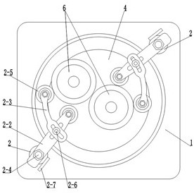
[0041] see figure 2, the large-area quartz wafer...


PUM


Abstract

A large-area quartz wafer grinding device and grinding method, the grinding device is provided with a base, a support arm assembly, a grinding disc, a rotating seat, a rotating motor, a loading block and a repairing ring; the base is arranged on a horizontal plane On the square base on the base, the support arm assembly is installed at both ends of the diagonal line of the base; the support arm assembly includes a swing arm, a swing arm shaft, a swing arm motor, an adjustable arm and a roller, and the lower end of the swing arm shaft is connected to The swing arm motor is connected, the upper end of the swing arm shaft is fixedly assembled with one end of the swing arm, the middle part of the swing arm is fitted with one end of the adjustable arm, and rollers are installed on the other end of the swing arm and the adjustable arm; the grinding disc is installed on on the rotating base; the rotating base is driven by a rotating motor; the loading block is set in the disk repairing ring, and the quartz wafer is bonded on the bottom surface of the loading block. The invention achieves the purpose of ensuring that the processing surface shape of the large-area quartz wafer meets the design requirements through the improved design of the two aspects of material removal and substrate holding.

Description

technical field [0001] The invention relates to a quartz wafer grinding device and a grinding method thereof, in particular to a grinding device and a grinding method for a large-area quartz wafer. Background technique [0002] Quartz single crystal thin substrate (referred to as quartz wafer) is the core component of the quartz crystal oscillator, and its performance index (such as the frequency value of the quartz crystal) is an important factor affecting the quality of the quartz crystal oscillator product. The surface quality and thickness of the wafer determine its frequency. The good surface quality of the quartz wafer can effectively improve the force-frequency characteristics of the resonator. Any tiny defects on the surface of the quartz wafer will affect the working accuracy and reliability of the components. The processing accuracy of quartz wafers has put forward nanometer-level requirements. [0003] During the processing of quartz wafers, grinding can be used ...

Claims


Application Information

Patent Timeline
Patent Type & Authority Patents(China)
IPC IPC(8): B24B37/10B24B37/005B24B49/00B24B37/30B24B49/16H03H3/02
CPCB24B37/10B24B37/005B24B49/006B24B37/30B24B49/16H03H3/02B24B37/044B24B37/105B24B37/34B24B37/32
Inventor 徐建民丁洁张勇王亮苏皓狄建兴郝建军张迎春王华恩张贤领崔立志
Owner TANGSHAN GUOXIN JINGYUAN ELECTRONICS CO LTD
Why Eureka
Try Eureka