
Direct pressure type primary-secondary cylinder of injection molding machine

A technology of direct pressure and master cylinder, which is applied in the field of direct pressure master cylinder of injection molding machine, which can solve the problems that affect the opening and closing of molds of injection molding machines, uneven force distribution, poor clamping effect, etc., and achieve high precision. Difficult to control, reduce material cost, and compact structure

Pending Publication Date: 2022-01-18
余姚市鹰图机械设备有限公司
View PDF1 Cites 0 Cited by
  • Summary
  • Abstract
  • Description
  • Claims
  • Application Information

AI Technical Summary

Problems solved by technology

[0005] The purpose of the present invention is to provide a direct pressure type sub-master cylinder for injection molding machines to solve the problem of poor mold clamping effect in the prior art, resulting in uneven distribution of force on the mold of the injection molding machine, which affects the opening and closing of the mold of the injection molding machine, and is practical. poor problem

Method used


Image

  • Direct pressure type primary-secondary cylinder of injection molding machine
  • Direct pressure type primary-secondary cylinder of injection molding machine
  • Direct pressure type primary-secondary cylinder of injection molding machine

Examples


Embodiment

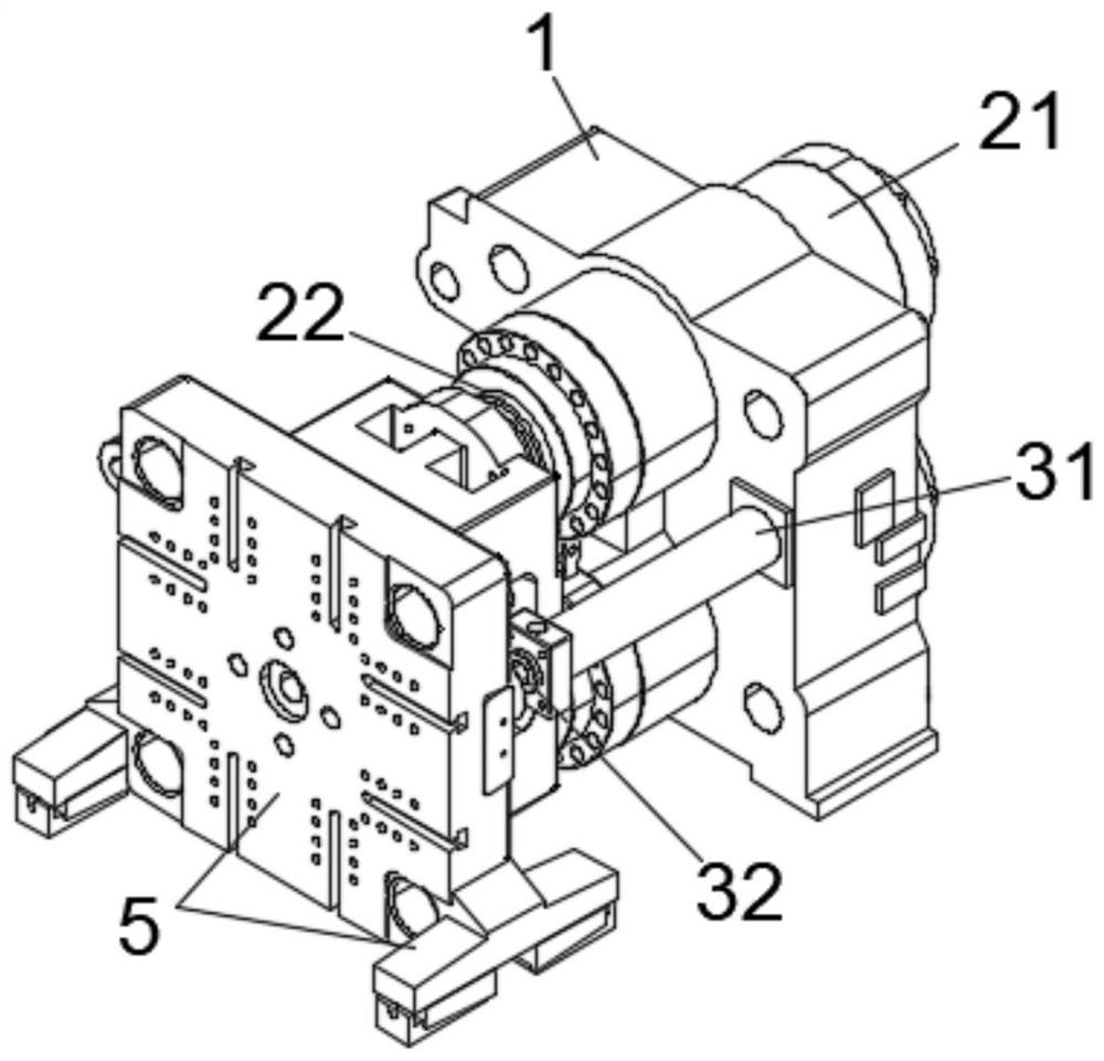
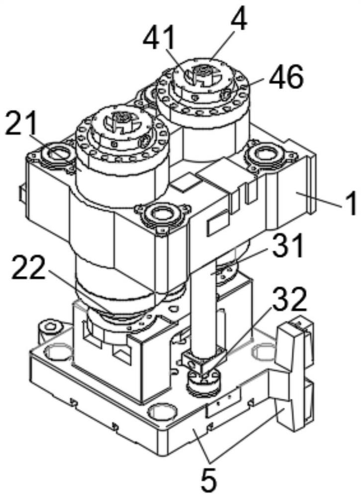
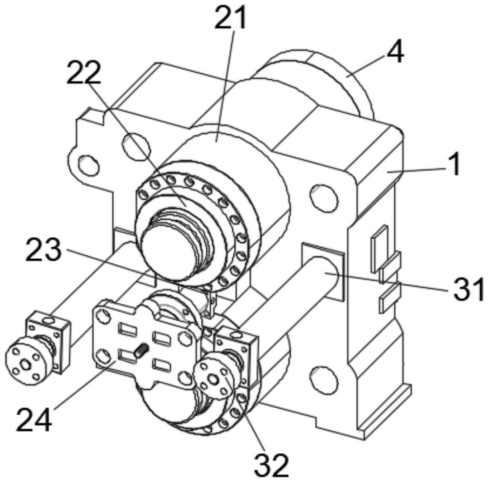
[0025] See Figure 1-6 , The present invention provides a direct pressure type injection molding machine cylinder picture aspect: the template 1 comprises, after the template is provided with a clamping cylinder 21 fitted, and is provided with suction pressurized clamping cylinder assembly 21, suction pressurized oil of the cylinder head assembly comprises a clamping cylinder provided at the tail 4 of 21, the end face of the cylinder head 4 is provided with an oil cap plate, a plurality of fixing holes provided on the cover plate, and is fixed by screws to the oil inlet orifice member 4 is connected to the cylinder head oil , 4 cylinder lid 21 and the clamping cylinder in communication with the oil feed member 41 on the cylinder head oil 4, the oil feed member is provided as a hole into fan-shaped distribution 41, and the oil feed member 41 and equipped with the cooperating movable column 43, column 43 is connected with a closed end surface active plate 44, positioned into the mova...


PUM


Abstract

The invention relates to the technical field of injection molding machines, and discloses a direct pressure type primary-secondary cylinder of an injection molding machine. The direct pressure type primary-secondary cylinder comprises a rear mold plate, mold locking oil cylinders are embedded in the rear mold plate, and oil suction pressurization assemblies are arranged on the mold locking oil cylinders. The oil suction pressurization assemblies comprise oil cylinder covers arranged at the tails of the mold locking oil cylinders, the oil cylinder covers communicate with the mold locking oil cylinders, oil inlet pieces are arranged on the oil cylinder covers, movable columns matched with the oil inlet pieces are arranged in the oil inlet pieces, first piston rods and pistons in the mold locking oil cylinders reciprocate, negative pressure is generated in oil storage cavities and oil cylinder cavities of the mold locking oil cylinders, in other words, sealing plates in the oil cylinder covers move, oil is sucked into the oil cylinder cavities from the oil inlet pieces, the sufficient power requirement of the mold locking oil cylinders is met, the mode that the mold locking oil cylinders are arranged in a split mode and the number of the mold locking oil cylinders is increased is adopted, the manufacturing cost is reduced, meanwhile, the mold locking oil cylinders are arranged in a distributed mode, acting points of mold locking force are also distributed, the stress points of a mold used by the injection machine are also in distributed stress, the mold locking force is more balanced under the same condition, and mold locking stability is guaranteed.

Description

Technical field [0001] The present invention relates to the technical field of injection molding machines, in particular to a direct pressure type injection molding machine cylinder picture. Background technique [0002] The injection molding machine is also known as a molding machine or a syringe. It is the main molding apparatus for making thermoplastic or thermoset plastics using plastic molding molds into various shapes of plastic products. Divided into vertical, horizontal, full-electric. The injection molding machine can heat the plastic, applying a high pressure to the molten plastic, making it shot and filled with a mold cavity. [0003] The working principle is similar to the injection molding machine with an injection syringe, which is by means of a screw (or plunger) of thrust, which has been plasticized in a molten state a good (i.e., viscous flow state) of the plastic injected into the mold cavity is closed good, dried shaping the article to obtain post-curing proces...

Claims


Application Information

Patent Timeline
Patent Type & Authority Applications(China)
IPC IPC(8): B29C45/67B29C45/17
CPCB29C45/67B29C45/1756
Inventor 唐亮亮
Owner 余姚市鹰图机械设备有限公司
Learn More