
Micron or nano aerosol particle enrichment device

An aerosol particle enrichment technology, applied in the direction of manufacturing auxiliary devices, additive processing, etc., can solve the problems of micron or nanometer aerosol particle enrichment accuracy and low efficiency, and achieve enhanced Safman lift effect, high-efficiency enrichment collection, effects with a wide range of effects

Active Publication Date: 2022-01-21
XI AN JIAOTONG UNIV
View PDF8 Cites 0 Cited by
  • Summary
  • Abstract
  • Description
  • Claims
  • Application Information

AI Technical Summary

Problems solved by technology

[0005] The object of the present invention is to overcome the disadvantages of low enrichment accuracy and efficiency of micron or nanometer aerosol particles in the above-mentioned prior art, and provide a kind of micron or nanometer aerosol particle enrichment device

Method used


Image

  • Micron or nano aerosol particle enrichment device
  • Micron or nano aerosol particle enrichment device
  • Micron or nano aerosol particle enrichment device

Examples


Embodiment 1

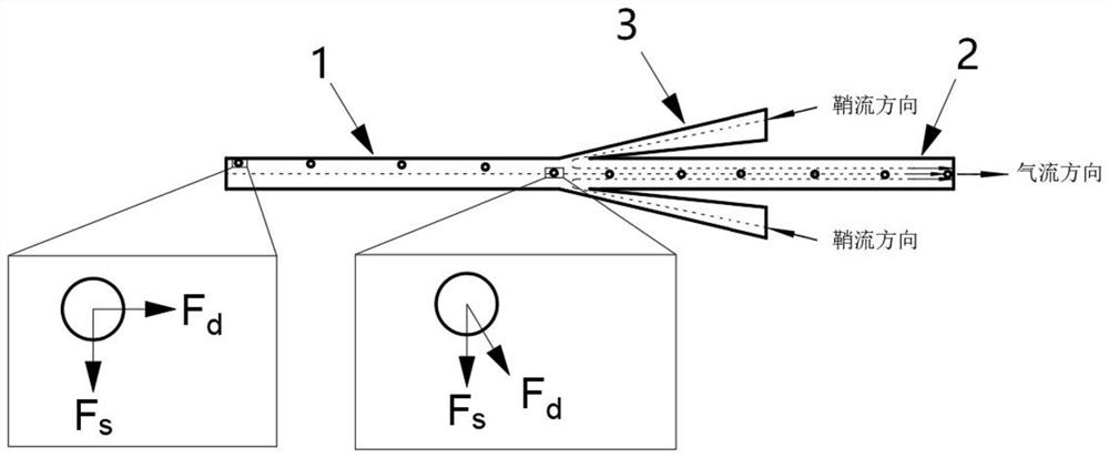
[0048] In this embodiment, two sheath airflow microchannels 3 are provided, and the two sheath airflow microchannels 3 are symmetrically disposed outside the aerosol particles enrichment microchannel 2, which is used to form symmetrical in aerosol particles. The gas stream at the center of the aerosol particles is enriched the center of the microchannel 2 and the speed zero point near the through hole. The aerosol particulate sample microchannel 1 and the aerosol particles enrichment microchannel 2 use small-channel width constant section, the direction of sheath in the sheath gas flow microchannel 3, and the aerosol particles are applied to microchannel 1 and aerosol particles. The airflow direction in the microchannel 2 is inversely, and there is a 2 ° angle, so that the spherner flow has a broader range, and the pressure varies near the outlet of the sheath gas flow microchannel 3 is more gentle, and the particles are hitting the wall. loss.

[0049] Specific verification proce...

Embodiment 2

[0052] The principles of the present embodiment are substantially the same as the above embodiment, and in the present embodiment, the effects of the enrichment of different sheath airflow structures on aerosol particles are verified, for example, forward sheath gave flow and reverse radiospheric stream. See Figure 4 The same sheath gas flow ratio and flow, micrometer or nanogenic sol particles in the positive sheath gas flow and the anti-radiator of the aerosol particles enrichment microchannel 2 exit enriched bandwidth, from Figure 4 It can be seen that the aerosol particles of the reverse sheath gas flow structure are more obvious to the enrichment of aerosol particles, because the reverse radiosphere provides a speed zero point near the spheric inflow, resulting in more As a strong speed gradient, the granules are larger than the Safang power of the center of the channel, and the reverse radopene flow also improves the pressure change in the vicinity of the spheric inflow, so ...


PUM

PropertyMeasurementUnit
widthaaaaaaaaaa

Abstract

The invention belongs to the technical field of aerosol enrichment, and discloses a micron or nano aerosol particle enrichment device which comprises an aerosol particle sample adding micro-channel, an aerosol particle enrichment micro-channel and a sheath airflow micro-channel. The airflow outlet side of the aerosol particle sample adding micro-channel is connected with the airflow inlet side of the aerosol particle enrichment micro-channel; a through hole is formed in the side wall of the aerosol particle enrichment micro-channel and is connected with the airflow outlet side of the sheath airflow micro-channel; a preset included angle is formed between the sheath airflow micro-channel and the aerosol particle enrichment micro-channel, the preset included angle is an acute angle, and the airflow inlet side of the sheath airflow micro-channel extends in the direction from the aerosol particle sample adding micro-channel to the aerosol particle enrichment micro-channel. By arranging the reverse sheath airflow micro-channel, micron or nano aerosol particles quickly move to the center position of the aerosol particle enrichment micro-channel, efficient enrichment is achieved, and great significance is achieved for improving the 3D printing precision and improving the performance of micro-nano components.

Description

Technical field [0001] The present invention belongs to aerosol enrichment technology, and involves a micrometer or nano-aerosol particulate enriched device. Background technique [0002] Micrometer or nanogenic sol particles are highly efficiently enriched in inkjet printing, environmental monitoring and biomedicine. As 3D printing adding materials based on microl or nanogenic sol particles, it can be used to prepare high-precision micro-structure and micro-circuit printing, improve the enrichment accuracy of aerosol, and improve printing accuracy, improve micro-nano component performance. significance. [0003] At present, the micrometer or nanogenic sol particulate enrichment method is mainly by using a forward sphericular or aerodynamic lens, and the aerosol particles are highly angled, and the radial drag force to the center of the channel is enriched. . The above method is simple, but there is a disadvantage that the channel is long, the enriched accuracy is not high and th...

Claims


Application Information

Patent Timeline
Patent Type & Authority Applications(China)
IPC IPC(8): B29C64/30B33Y30/00
CPCB29C64/30B33Y30/00
Inventor 赵亮王尧范亮亮
Owner XI AN JIAOTONG UNIV
Learn More