Unlock instant, AI-driven research and patent intelligence for your innovation.

New energy automobile high-speed driving motor shaft

A technology of new energy vehicles and high-speed motors, applied in the direction of motors, electric vehicles, brake actuators, etc., can solve problems such as the influence of heat and centrifugal force bearings, achieve the effects of reducing impact force, reducing quality, and prolonging service life

Active Publication Date: 2022-01-21
HANGZHOU SAIQI MACHINERY CO LTD
View PDF6 Cites 1 Cited by
  • Summary
  • Abstract
  • Description
  • Claims
  • Application Information

AI Technical Summary

Problems solved by technology

[0004] Based on this, it is necessary to address the above problems and propose a high-speed drive motor shaft for new energy vehicles that can fully and effectively dissipate heat according to the rotational speed, overcome the negative effects of centrifugal force, and ensure high-speed rotation, so as to solve the above-mentioned problems in the background technology. There is a problem that high-speed rotation will generate a lot of heat and centrifugal force will negatively affect the bearing in the technology

Method used


Image

  • New energy automobile high-speed driving motor shaft
  • New energy automobile high-speed driving motor shaft
  • New energy automobile high-speed driving motor shaft

Examples


Embodiment 1

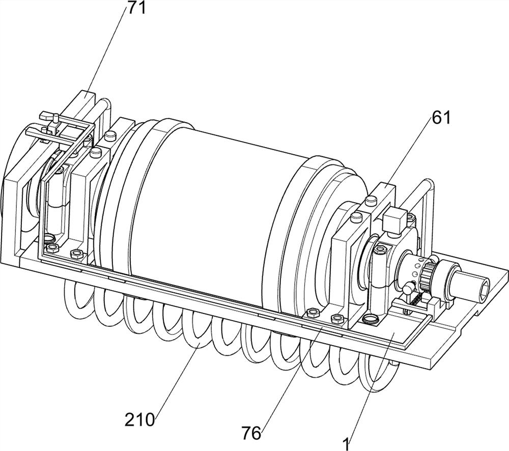
[0042] A motor shaft driven by a new energy vehicle at high speed, such as figure 1 , figure 2 , image 3 , Figure 4 , Figure 5 , Image 6 , Figure 7 , Figure 8 , Figure 9 , Figure 10 , Figure 11 , Figure 12 and Figure 13 As shown, it includes a U-shaped connecting plate 1, a lubricating and cooling high-speed driving part 2, a power cutting part 3 and a position calibration part 4. The U-shaped connecting plate 1 is provided with a lubricating and cooling high-speed driving part 2, which is used for the lubricating and cooling high-speed driving part 2. To cool down while lubricating, the U-shaped connecting plate 1 is provided with a power cut-off part 3, which is used to cut off the power between the motor and the drive shaft, and the U-shaped connecting plate 1 is provided with a position calibration part 4 , the position calibration component 4 is used to speed up the lubrication and cool down after the power is cut off, and the high-speed driving com...

Embodiment 2

[0049] On the basis of Example 1, such as Figure 14 and Figure 15 As shown, it also includes a heat dissipation power adjustment part 5, the heat dissipation power adjustment part 5 is arranged on the high-speed motor shaft body 25, and the heat dissipation power adjustment part 5 is used to adjust the heat dissipation efficiency according to the speed of the high-speed motor shaft body 25 and the device on it. The power adjustment component 5 includes a centrifugal disc 51, a conductive block 52, a first tension spring 53, a power supply plate 54 and a resistance plate 55, and the end of the high-speed motor shaft 25 away from the inner six-slot spline drive shaft 33 is fixedly connected with the centrifugal disc 51 A conductive block 52 is slidably connected to the groove on the centrifugal disc 51. The conductive block 52 is used to conduct current to the oil well pump 29. A first tension spring 53 is connected between the conductive block 52 and the centrifugal disc 51. ...

Embodiment 3

[0052] On the basis of Example 2, such as Figure 16 As shown, it also includes a transverse support component 6, which is arranged on the U-shaped connecting plate 1, and the transverse support component 6 is used to ensure that the high-speed motor shaft body 25 can rotate at a stable high speed. The transverse support component 6 includes a transverse bearing Seat 61, oil filling port 62, ball 63 and bearing ring 64, a pair of transverse bearing seats 61 are connected by bolts on the left and right sides of the top of the U-shaped connecting plate 1, and the pair of transverse bearing seats 61 on the same side are closely fitted, and the transverse bearing seats An oil injection port 62 is provided above 61, and the oil injection port 62 is used to allow hydraulic oil to enter the interior of the device. A pair of bearing rings 64 are connected to the shaft body 25 of the high-speed motor in an interference fit. The bearing rings 64 are rotationally connected to the transver...


PUM


Abstract

The invention relates to the field of new energy automobiles, in particular to a new energy automobile high-speed driving motor shaft. The new energy automobile high-speed driving motor shaft comprises a U-shaped connecting plate, a lubricating and cooling high-speed driving component, a power cut-off component, a position calibration component and the like. The U-shaped connecting plate is provided with the lubricating and cooling high-speed driving component, the power cutting-off component and the position calibration component. Through cooperation of cylindrical supporting rollers, balls and devices on the balls, a high-speed motor shaft body can bear large impact force due to the fact that the cylindrical supporting rollers longitudinally support the high-speed motor shaft body, and the balls transversely support the high-speed motor shaft body, friction force of the high-speed motor shaft body during high-speed rotation can be small; and the longitudinal support and the transverse support are matched with each other, so that the high-speed motor shaft body ensures high-speed rotation while bearing multi-directional centrifugal force, and safe and stable high-speed rotation of the high-speed motor shaft body is ensured.

Description

technical field [0001] The invention relates to the field of new energy vehicles, in particular to a high-speed drive motor shaft for new energy vehicles. Background technique [0002] In recent years, new energy vehicles have developed rapidly. As the power source of new energy vehicles, the motor bearing is a special bearing specially used on the motor, and the motor shaft is an important part of the motor. The link of electromechanical energy conversion is used to support the rotating parts, transmit torque and determine the relative position of the rotating parts to the stator, and the motor shaft will rotate at high speed. Therefore, the motor shaft must have reliable strength and rigidity to ensure the preset design function realization. [0003] The motor shaft has an inseparable relationship with the high-speed motor. The motor shaft will generate a lot of heat when it rotates at high speed. If the motor shaft is not cooled in a reasonable way, it will cause it to e...

Claims


Application Information

Patent Timeline
IPC IPC(8): F16C3/02F16D1/08F16H57/00F16H57/04F16D65/06F16D65/14H02K7/00H02K9/193F16D121/14
CPCF16C3/02F16D1/08F16H57/0025F16H57/0037F16H57/0417F16H57/0413F16H57/043F16H57/0434F16D65/06F16D65/14H02K7/003H02K9/193F16D2121/14Y02T10/64
Inventor 武瑞娜
Owner HANGZHOU SAIQI MACHINERY CO LTD