High-precision magnetic imaging system and method based on TMR sensor

A high-precision, magnetic imaging technology, applied in instruments, scientific instruments, and material analysis through electromagnetic means, can solve problems such as limiting the scope of application, and achieve the effects of flexible operation, low power consumption, and simple operating procedures

Pending Publication Date: 2022-01-21
XI AN JIAOTONG UNIV
View PDF7 Cites 0 Cited by
  • Summary
  • Abstract
  • Description
  • Claims
  • Application Information

AI Technical Summary

Problems solved by technology

The contradiction between sensitivity and detection depth also causes eddy current flaw detection to only be used for the detection of thin-layer structures such as plates and pipes, which limits its application range

Method used


Image

  • High-precision magnetic imaging system and method based on TMR sensor
  • High-precision magnetic imaging system and method based on TMR sensor
  • High-precision magnetic imaging system and method based on TMR sensor

Examples


Embodiment

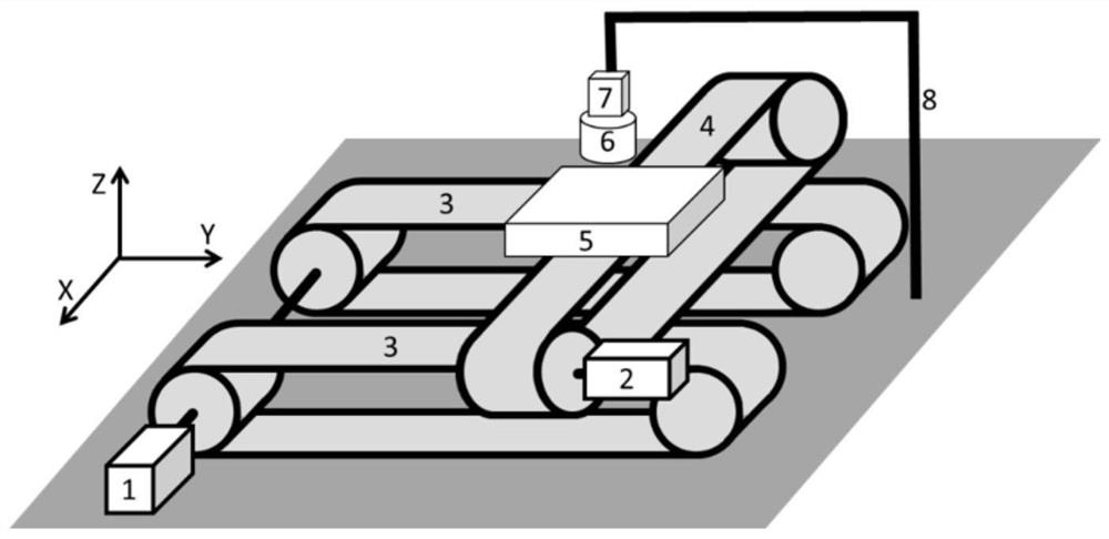
[0071] figure 1 It is a mechanical structure link method;

[0072] 1 is the X-axis stepping motor, 2 is the Y-axis stepping motor, 3 is the X-axis guide rail, 4 is the Y-axis guide rail, 5 is the liftable sample stage, 6 is the excitation coil; 7 is the full-bridge TMR linear magnetoresistive sensor, The sensitive axis is placed along the Z axis; 8 is the bracket;

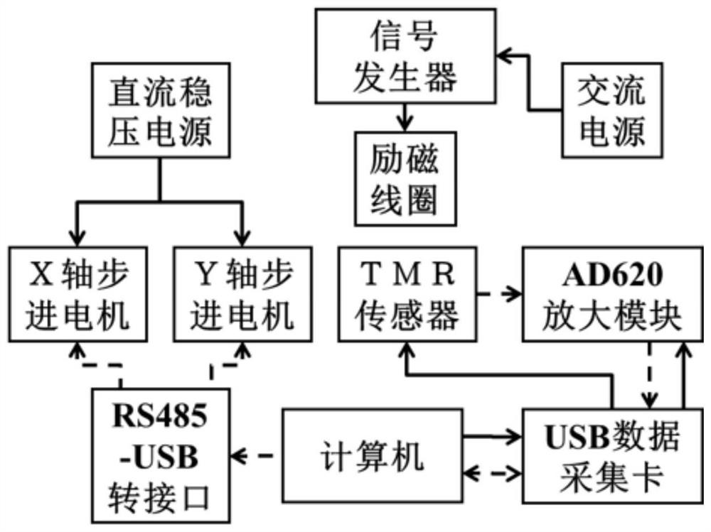
[0073] figure 2 It is the circuit and signal link mode, the solid line represents the power supply line, and the dotted line represents the signal line;

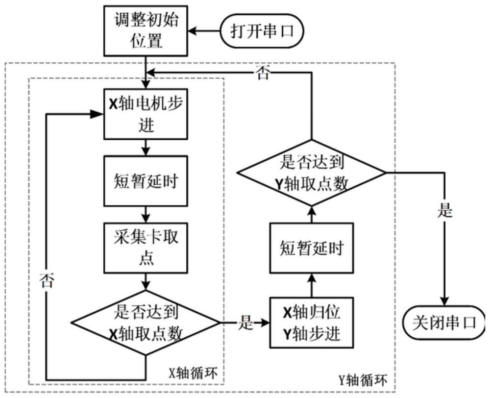
[0074] image 3 It is a basic logic structure diagram of the computer-side control program.

specific Embodiment approach

[0075] Step 1: Structure Construction

[0076] X-axis parallel double guide rails and Y-axis guide rails are vertically built, driven by X-axis and Y-axis stepping motors respectively;

[0077] The stepper motor driver adopts RS485 protocol, and is connected to the computer through the RS485 to USB interface;

[0078] The stepper motor provides +25V power supply through a DC regulated power supply;

[0079] The excitation coil provides an excitation signal through an AC signal source and applies excitation to the sample, and the axial direction is perpendicular to the sample stage, that is, along the Z-axis direction;

[0080] The TMR sensor provides 0-5V single-ended power supply through the analog output of the data acquisition card, and is placed above the excitation coil. The sensitive axis is consistent with the axis of the excitation coil, that is, along the Z-axis direction;

[0081] The AD620 amplifier module provides +5V single-ended power supply through the power s...


PUM


Abstract

The invention discloses a high-precision magnetic imaging system and method based on a TMR sensor. The high-precision magnetic imaging system comprises a two-dimensional mobile platform, a sensing module, a data acquisition module and an automatic control module, wherein the sensing module is located above the two-dimensional mobile platform, and the automatic control module is connected with the sensing module through the data acquisition module; the two-dimensional mobile platform drives a sample to scan and move along a two-dimensional direction, the sensing module performs eddy current excitation and magnetic signal acquisition, the data acquisition module preprocesses the signal and sends the signal to the automatic control module, and the automatic control module further calculates and processes the magnetic signal, outputs a magnetic field image to the interaction interface, and controls the scanning platform and the data acquisition assembly to work. According to the invention, the application of TMR in the field of two-dimensional magnetic imaging is supplemented, the eddy current detection technology is perfected, and the sensitivity and detectable depth are further improved. And meanwhile, two-dimensional imaging of high-precision weak magnetic signals under a non-eddy current condition can be completed. The system has the advantages of high sensitivity, high precision, low power consumption, simple structure and controllable cost.

Description

technical field [0001] The invention belongs to the technical field of high-precision magnetic imaging, and in particular relates to a high-precision magnetic imaging system and method based on a TMR sensor. Background technique [0002] Magnetic sensing technology: At present, magnetic sensing technology can be mainly divided into detection coils, fluxgates, Hall elements, magnetoresistive sensors, superconducting quantum interference magnetic sensors (SQUIDs) and magneto-optical devices. The detection coil is the most commonly used method in eddy current magnetic imaging; in comparison, the fluxgate, which is also based on the principle of electromagnetic induction, realizes more accurate magnetic field detection in a more complicated way; the SQUIDs sensor is currently the most sensitive magnetic field sensor, reaching fT level, which works in a low-temperature superconducting state; magneto-optical devices are based on the influence of magnetic fields on optical informat...

Claims


Application Information

Patent Timeline
Patent Type & Authority Applications(China)
IPC IPC(8): G01N27/9013
CPCG01N27/902
Inventor 刘明胡忠强吴金根关蒙萌刘佳明王立乾
Owner XI AN JIAOTONG UNIV
Why Eureka
Try Eureka