

Thread detection method based on three-dimensional modeling
A three-dimensional, detection method technology, applied in the field of thread detection and thread virtual detection, can solve the problems of inspection error, time-consuming, labor-intensive, etc., and achieve the effect of simple and tedious work, simple and easy method, and accurate detection.
- Summary
- Abstract
- Description
- Claims
- Application Information
AI Technical Summary
Problems solved by technology
Method used
Image


Examples
Embodiment 1
[0063] In this example, see Figure 1-Figure 6 , a thread detection method based on three-dimensional modeling, which establishes two triangulated models of plug gauge helicoids with different sizes, and uses these two triangulated models to detect the actual internal thread scanning point cloud in the same way as the external thread detection method. Including the following steps:
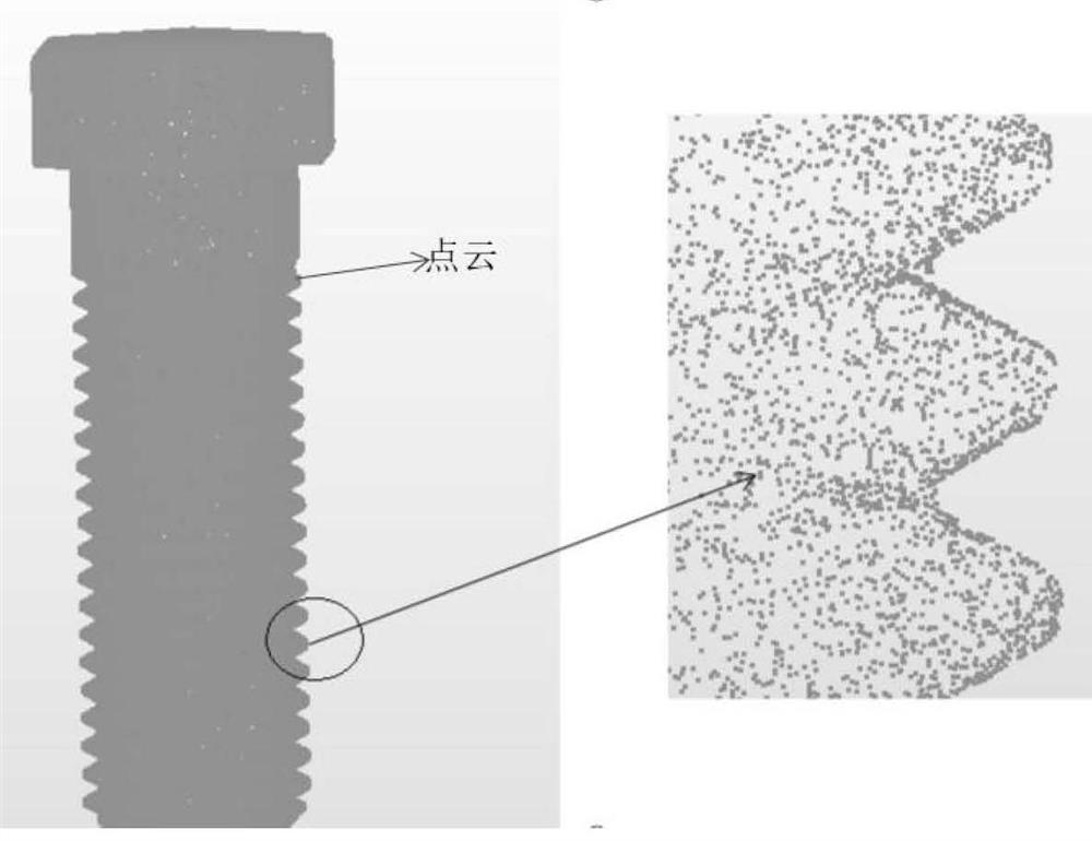
[0064] (1) Obtain the actual measured 3D scanning point cloud of the detected thread:
[0065] Through the information collection and information preprocessing of the detected thread, the actual measured 3D scanning point cloud of the detected thread is obtained as the actual measured point cloud to be matched;
[0066] (2) Establish the helicoid triangulation model of the go-gauge and the stop-gauge:
[0067] According to the use method of the go-no-go gauge used in the actual inspection, the helical surface triangulation model of the go-gauge and the no-go gauge with the tooth profile aligned ...
Embodiment 2
[0074] This embodiment is basically the same as Embodiment 1, especially in that:
[0075] In this embodiment, in the step (3), by translating the rotation matrix, the overall point cloud is translated and rotated around the axis of the CAD model or the axis of the triangulated model of the general helicoid, simulating the actual screw thread engagement The spiral progress of the process corresponds to the screwing process when the thread is actually inspected with the go-gauge and stop gauge, and is used to measure different positions of the actual measurement point cloud.
[0076] In the present embodiment, in the step (2), the positive or negative of the distance from the point of the actually measured point cloud to the triangular surface of the triangulated model is defined, and the direction of the surface of the triangulated model of the general helical surface is set to face inwards. The surface direction of the regular helical surface triangulation model is set to fac...
Embodiment 3
[0103] This embodiment is basically the same as the above-mentioned embodiment, and the special features are:
[0104] In this example,
[0105] Such as figure 2 Shown is a triangulated model of the go-no-go helicoid, with the face oriented inward and the face oriented outward. image 3 The CAD model has the same ideal tooth shape as the triangularized model of the general gauge, and the pitch diameter is between the triangularized model of the general gauge and the anti-helical surface. Figure 4 It is the actually measured and preprocessed point cloud, which contains the spatial x, y, and z coordinates of each point on the actual thread surface.
[0106] First, the actual measurement point cloud and the CAD model are registered. Firstly, rough registration is performed, and after coarse registration, fine registration randomly samples enough points on the point cloud and the surface of the CAD model. These points are not connected at first. It is necessary to find the co...
PUM
 Abstract
Description
Claims
Application Information