Cavity film with film stretching frames and cavity film hollow glass

A stretch film frame and cavity technology, applied in the field of continuous production equipment, can solve problems such as the complex structure of the diaphragm insulating glass, the difficulty of combined packaging and processing, and the impact on the effect of heat insulation, etc., to solve the problem of corner wrinkling and middle part Effects of collapse, reduced manufacturing costs, and improved productivity and performance

Pending Publication Date: 2022-01-25
QINGDAO TECHNOLOGICAL UNIVERSITY
View PDF0 Cites 0 Cited by
  • Summary
  • Abstract
  • Description
  • Claims
  • Application Information

AI Technical Summary

Problems solved by technology

However, due to the complexity of its processing technology, it is difficult to combine with glass, resulting in many problems such as low production efficiency and unstable quality.
[0004] The structural characteristics of the existing diaphragm insulating glass determine that its structure is too complex, the production process is cumbersome, and the production and processing are difficult
Therefore, since the industrial production of diaphragm insulating glass, the insertion of elastic elements, the fixing and te

Method used


Image

  • Cavity film with film stretching frames and cavity film hollow glass
  • Cavity film with film stretching frames and cavity film hollow glass
  • Cavity film with film stretching frames and cavity film hollow glass

Examples


Embodiment 1

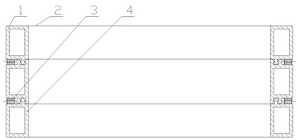
[0054] Example 1: Reference figure 1 A cavity film having a flux frame comprising a spacer frame 1, two diaphragm 2, and two strand frames 4, two of the four sides of the diaphragm 2 are fixed to the interval On the frame 1, the remaining two pairs are not fixed in a free state, or the four edges of the separator 2 are fixed to the space frame 1, four corners or not fixed, the angle is made by cut angles, punching or slots. The portion is free, preventing a wrinkle in the corner of the diaphragm; the two diaphragms 2 are fixed to both sides of the spacer frame 1, the diaphragm 2, the spacer frame 1 and the separator 2 form a cavity, which constitutes a cavity film; two The outer side of the diaphragm 2 has a flirtraum frame 4, and the spacing frame 1 is mounted on the surface of the sliding frame 4, and the convex and concave structure is located in the inside of the diaphragm 2, in the sliding frame 4 and the interval. When the frame 1 is pressed, the convex and concave structure...

Embodiment 2

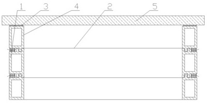
[0056] Example 2: Reference figure 2 A single glass cavity film made of a cavity film having a flux frame, including a glass 5 and a cavity film having a slacete frame, cavity film having a flip frame and glass 5 by sealing The glue 3 is bonded together into a single glass cavity membrane in hollow glass.

[0057] The monolithic cavity of the monochrome cavity can be used directly to create a flat solar water heater cover or a freezer or an insulation plate of the wine cabinet or a thermal glass in which a double glass cavoline can be used.

Embodiment 3

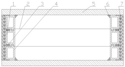
[0058] Example 3: Reference image 3 A double glass cavity membrane manufactured by a slope frame and cavity membrane, including two glass 5, two strand frames 4, and a cavity film, first fabricated in Example 1. 4 and a cavity film, then produce two kinds of glass 5, and then applied to the sealing glue 3 on both sides of the two flip frames 4, fixed on two glass 5, and in the flunter frame 4 The inner ring or outer ring is placed onto the glass contact, so that the slacete frame 4 is quickly firmly bonded to the glass 5, preventing the slacete of the slimming frame 4 from moving; Two pieces of glass 5 with the sliding frame 4 are pressed, and the convex and concave structure on the space frame 1 and the slacete 4 is simultaneously fitted with each other, and the film 5 and the stretch The structural adhesive 7 is applied in the space formed in the outer side of the membrane frame 4 and the cavity film, and the structural adhesive 7 can be used with silicone or polysulfide or hot ...


PUM


Abstract

The invention discloses a cavity film with film stretching frames. The cavity film comprises a spacing frame, two diaphragms and two film stretching frames, the two diaphragms are respectively fixed on two sides of the spacing frame, and a cavity is formed among the diaphragms, the spacing frame and the diaphragms to form the cavity film; and the outer sides of the two diaphragms are respectively provided with one film stretching frame, the spacing frame and the film stretching frames are provided with convex-concave structures which are matched with each other, and when the film stretching frames and the spacing frame are pressed, the convex-concave structures are embedded with each other, so that the diaphragms can be stretched. The invention further discloses cavity film hollow glass. The cavity film hollow glass comprises the cavity film with the film stretching frames and two pieces of glass, the two pieces of glass are pasted on the two sides of the cavity film, and the space formed by the two pieces of glass and the outer side of the cavity film is fully coated with the structural adhesive. The invention further provides a manufacturing method of the cavity film and the cavity film hollow glass. The manufacturing method has the characteristics of being simple in process, convenient to manufacture, low in cost and large in productivity.

Description

Technical field [0001] The present invention belongs to the field of hollow glass, and more particularly to a cavity membrane and cavity membrane in cavity films and a cavity membrane in a cavity and a continuous production apparatus. Background technique [0002] With the development of green energy-saving buildings, it has been increasingly high-increasing the heat insulation performance of the glass used. It has gradually developed from the original single cavity in hollow glass or even in the three-cavity of four vagumes. The increase in the hollow cavity, the problem is that the thickness and weight of the glass increases, the cost of the framework and the hardware also increases, so the cost of the doors and windows is also increased; and the optical plastic film is used instead of double cavity or more The technology of intermediate glass in cavity has been gradually accepted by users and markets. Since the optical plastic film has the same optical properties as ultra-thin...

Claims


Application Information

Patent Timeline
IPC IPC(8): E06B3/67E06B3/663E06B3/667F24S10/40F25D23/02C03C27/12
CPCE06B3/6715E06B3/6707E06B3/66309E06B3/667F24S10/40F25D23/02C03C27/10Y02E10/44Y02B10/20
Inventor 孙好芬戴长虹
Owner QINGDAO TECHNOLOGICAL UNIVERSITY
Why Eureka
Try Eureka