Computer vision method and intelligent camera system for bridge health diagnosis

A computer vision and bridge technology, applied in computing, neural learning methods, image analysis, etc., can solve the problems of low image recognition accuracy, poor real-time performance, and low efficiency, and achieve good real-time performance, high accuracy, and slow solution speed Effect

Active Publication Date: 2022-01-25
HARBIN INST OF TECH
View PDF8 Cites 5 Cited by
  • Summary
  • Abstract
  • Description
  • Claims
  • Application Information

AI Technical Summary

Problems solved by technology

[0005] In order to solve the problems of low image recognition accuracy, poor real-time performance and low efficiency for bridge health diagnosis in the prior art, the present invention provides a computer vision method and an intelligent camera system for bridge health diagnosis

Method used


Image

  • Computer vision method and intelligent camera system for bridge health diagnosis
  • Computer vision method and intelligent camera system for bridge health diagnosis
  • Computer vision method and intelligent camera system for bridge health diagnosis

Examples


Embodiment approach 1

[0078] Embodiment 1, see figure 1 This embodiment will be described. This embodiment provides a computer vision method for bridge health diagnosis, and the method includes:

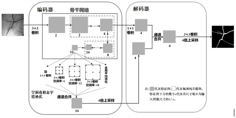
[0079] Step 1. Establish a lightweight semantic segmentation deep convolutional neural network model for multiple types of bridge defects, which includes an encoder and a decoder;

[0080] The encoder includes a backbone network and dilated convolutional pyramid pooling;

[0081] The backbone network includes a convolution module and several bottleneck residual modules, the first layer is the convolution module, and the convolution module is used to extract low-level features from the input image, and output low-level feature maps to the first a bottleneck residual module;

[0082] The several bottleneck residual modules are connected in sequence, and each bottleneck residual module sequentially reduces the size of the feature map output by the previous layer according to the preset value and performs ...

Embodiment approach 2

[0099] Embodiment 2. This embodiment is a further limitation of the computer vision method for bridge health diagnosis described in Embodiment 1. In this embodiment, the preset values ​​and preset reduction conditions related to reducing the size of the input image in the backbone network Further restrictions are made, specifically:

[0100] The size of the low-level feature map is 1 / 2 the size of the input image;

[0101] The preset values ​​are 1 / 4, 1 / 8 and 1 / 16 of the input image;

[0102] The preset reduction condition is specifically to reduce the size of the feature map output by the previous layer to 1 / 16 of the input image.

[0103] Such as figure 1 As shown, the numbers 2, 4, 8, and 16 below the feature map mean that the size of the feature map at this level is reduced to 1 / 2, 1 / 4, 1 / 8, and 1 / 16 of the input image size, that is, the higher the level The size of the feature map is gradually reduced, and the number of layers increases with the direction of the arrow,...

Embodiment approach 3

[0107] Embodiment 3. This embodiment is a further limitation of the computer vision method for bridge health diagnosis described in Embodiment 2. In this embodiment, the bottleneck residual module is further limited, specifically:

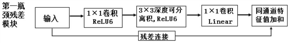
[0108] The bottleneck residual module includes a first bottleneck residual module and a second bottleneck residual module;

[0109] The step size of the second bottleneck residual module is twice the step size of the first bottleneck residual module.

[0110] It should be noted that choosing a relationship of 2 times can prevent over-sampling, and the high information loss rate will affect the accuracy rate; this design can realize the acquisition of multi-scale feature maps, and different step lengths can be used to obtain feature maps of different scales. Increase the ability to extract features from input images.

[0111] In this embodiment, the step size of the first bottleneck residual module can be set to 1, and the step size of the second b...


PUM


Abstract

The invention discloses a computer vision method and an intelligent camera system for bridge health diagnosis, belongs to the technical field of bridge health monitoring, and solves the problems of low image recognition precision, poor real-time performance and low efficiency of bridge health diagnosis in the prior art. The method comprises the following steps: establishing a lightweight semantic segmentation deep convolutional neural network model for bridge multi-type diseases; establishing an image data set of the multi-type diseases of the bridge, and obtaining a trained lightweight semantic segmentation deep convolutional neural network model of the multi-type diseases of the bridge; and collecting a bridge image in real time, and obtaining a semantic segmentation result graph of the bridge image. The method and the system are suitable for monitoring and detecting the health conditions of multiple types of bridge diseases online in real time, and can directly carry or integrate an integrated part of image acquisition, analysis and calculation and result display on inspection equipment such as an unmanned aerial vehicle, a robot, a detection vehicle and the like, so that automatic acquisition and intelligent identification of bridge disease images are realized.

Description

technical field [0001] The present application relates to the technical field of bridge health monitoring, in particular to a computer vision method and an intelligent camera system for bridge health diagnosis. Background technique [0002] Large bridges are important infrastructures of a country and region. Due to the coupling of complex factors such as environmental erosion, material aging, and fatigue effects caused by reciprocating loads, structural diseases (such as Concrete cracks, concrete spalling, steel fatigue cracks, etc.) and deformation (such as over-limit vibration, main beam deflection, support void, etc.). The continuous accumulation of bridge structural damage and deformation will directly threaten the service safety, and even lead to extreme disasters in severe cases. Therefore, bridge health monitoring and detection is very necessary to ensure the service safety of large bridge structures. [0003] Traditional bridge health monitoring and testing is main...

Claims


Application Information

Patent Timeline
Patent Type & Authority Applications(China)
IPC IPC(8): G06T7/00G06N3/04G06N3/08
CPCG06T7/0002G06N3/08G06T2207/20081G06T2207/20084G06T2207/30132G06N3/045
Inventor 李惠徐阳张东昱乔威栋
Owner HARBIN INST OF TECH
Why Eureka
Try Eureka