Bone meal collector and dental handpiece applying bone meal collector
A dental handpiece and collector technology, applied in dentistry, dental drilling, dental tools, etc., can solve problems such as waste of bone powder, achieve the effects of improving safety, reducing burden, and increasing bone mass
- Summary
- Abstract
- Description
- Claims
- Application Information
AI Technical Summary
Problems solved by technology
Method used
Image

Examples
Embodiment 1
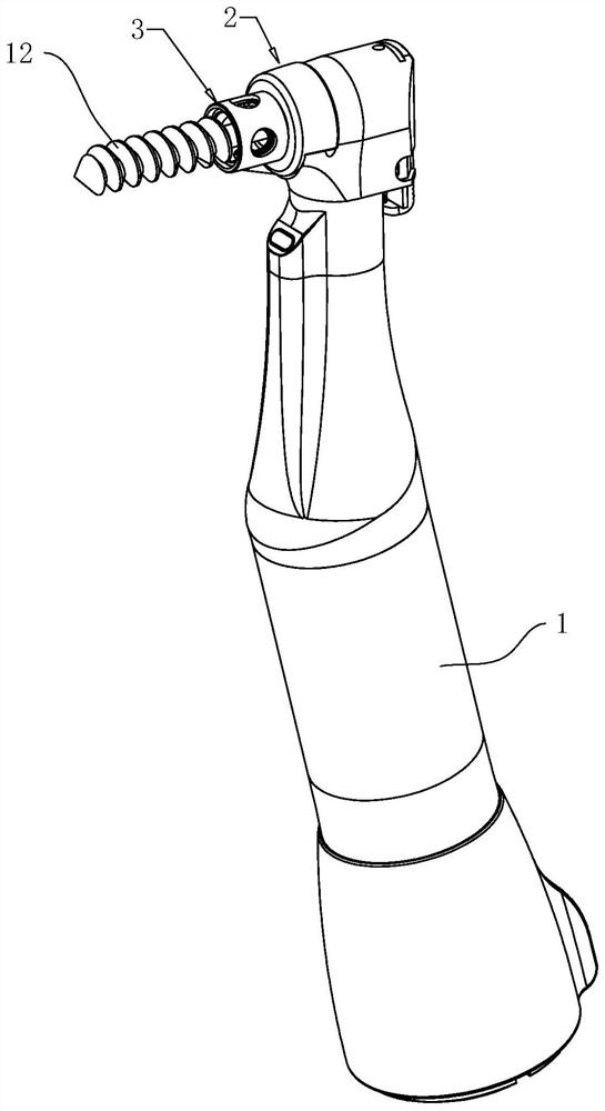
[0044] like figure 1 As shown, a bone meal collector includes a mounting assembly 2 and a collection sleeve 3, the mounting assembly 2 is connected to the dental handpiece body 1, and the collection sleeve 3 is connected to the dental handpiece body 1 through the mounting assembly 2, so that the collection sleeve 3 can be placed on the dental handpiece body 1 is installed and disassembled, the collection cover 3 is arranged around the dental drill 12 of the dental handpiece body 1, and the collection cover 3 is used to collect bone powder.
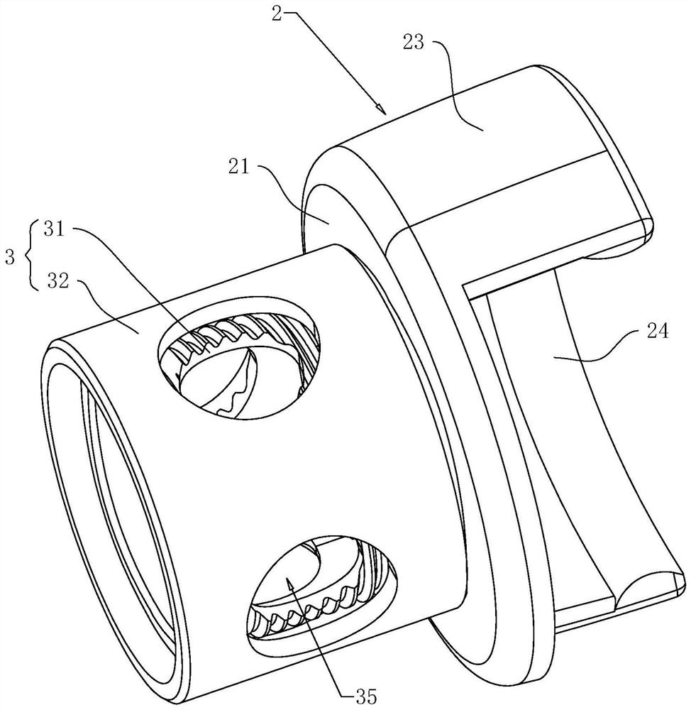
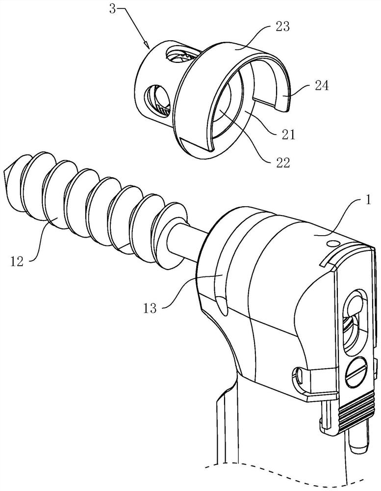
[0045] like figure 2 and image 3 As shown, there can be many kinds of mounting components 2, such as bolts, and the collecting sleeve 3 is fixedly connected to the dental handpiece body 1 through bolts. 23 and reinforcement bar 24, the section of mounting plate 21 is circular, and mounting plate 21 is positioned at the side that dental handpiece body 1 is provided with dental drill 12, and mounting plate 21 is provided with perforation...
Embodiment 2
[0058] like Figure 7 As shown, the difference between Embodiment 2 and Embodiment 1 is that the threaded connection between the inner sleeve 31 and the outer sleeve 32 is different. In this embodiment, the outer sleeve 32 is fixedly connected to the mounting plate 21, and the inner sleeve 31 is movably connected to the mounting plate 21. , the boss 33 is arranged on the outer wall of the inner sleeve 31, the boss 33 is located at one end of the inner sleeve 31 close to the mounting plate 21, the outer thread is arranged on the boss 33, the inner thread is arranged on the inner wall of the outer jacket 32, and the inner thread is arranged along the axis of the outer jacket 32 The inner thread and the outer thread are screwed together to realize the adjustment of the relative position of the inner sleeve 31 and the outer sleeve 32; the surrounding edge 34 is arranged on the end of the outer sleeve 32 away from the mounting plate 21, and the surrounding edge 34 is located on the ...
Embodiment 3
[0062] like Figure 8 As shown, the difference between the third embodiment and the first embodiment is only that the adjustable connection between the inner sleeve 31 and the outer sleeve 32 is different. In this embodiment, the inner sleeve 31 and the outer sleeve 32 are not provided with internal threads or external threads. The cover 31 is slidingly connected with the outer cover 32, and the side wall of the outer cover 32 is provided with an adjustment groove 4, and the adjustment groove 4 is arranged along the axial direction parallel to the dental drill 12; the outer wall of the inner cover 31 is fixed with an adjustment rod 41, and the side of the adjustment rod 41 The wall is provided with threads, and the adjusting rod 41 is passed through the adjusting groove 4, and the adjusting rod 41 is slidably connected to the inner wall of the adjusting groove 4; the part of the adjusting rod 41 protruding from the adjusting groove 4 is threaded with a nut 42, and the nut 42 is...
PUM
 Abstract
Description
Claims
Application Information
 - R&D
- Intellectual Property
- Life Sciences
- Materials
- Tech Scout
- Unparalleled Data Quality
- Higher Quality Content
- 60% Fewer Hallucinations
Browse by: Latest US Patents, China's latest patents, Technical Efficacy Thesaurus, Application Domain, Technology Topic, Popular Technical Reports.
© 2025 PatSnap. All rights reserved.Legal|Privacy policy|Modern Slavery Act Transparency Statement|Sitemap|About US| Contact US: help@patsnap.com