
Ionic membrane caustic soda first-effect evaporation device and method

An ion-membrane caustic soda and high-efficiency evaporation technology, applied in the field of caustic soda evaporation, can solve problems such as the inability of the evaporation system to run normally, the product concentration cannot be reached, and the production capacity of the device is affected, so as to reduce the maintenance and repair workload, and the production guarantee is strong and not easy. The effect of the material

Pending Publication Date: 2022-01-28
昊华宇航化工有限责任公司
View PDF0 Cites 0 Cited by
  • Summary
  • Abstract
  • Description
  • Claims
  • Application Information

AI Technical Summary

Problems solved by technology

[0002] The caustic soda evaporation process includes cauldron method, multi-effect co-current or counter-current natural circulation method, single- and double-effect rotary film method, multi-effect co-current or counter-current plate evaporation. The transmission force of the traditional evaporation process is 0.8MPa, 180°C (index 0.75- 0.85Mpa, 178-185℃), the first-effect evaporator adopts a plate evaporator, and under the conditions of the highest steam pressure, temperature, and alkali concentration, due to the aging and corrosion of the gasket, the leakage between the plates is caused. As a result, the evaporation system cannot operate normally, or the temperature of the discharge lye needs to be strictly controlled, and the concentration of the final product cannot reach 50%, only about 46%.
[0003] For a long time, most companies in the industry have been trying to overcome this problem, but they have not made substantial progress. They can only maintain production by regularly replacing gaskets and plates. The running time of the equipment is short and frequent maintenance is required, resulting in high maintenance costs. , affecting the production capacity of the device, resulting in a decline in production capacity

Method used


Image

  • Ionic membrane caustic soda first-effect evaporation device and method

Examples


Embodiment Construction

[0017] The scheme of the patent of the present invention will be described in detail below in conjunction with specific examples.

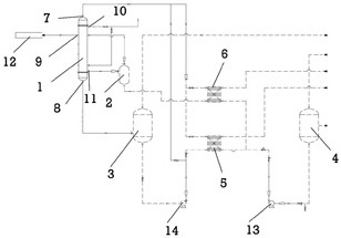
[0018] Such as figure 1 , an ionic membrane caustic soda one-effect evaporator, comprising a first-effect evaporator 1, a condensed water tank 2, a first-effect separator 3, a second-effect separator 4, a first-stage preheater 5 and a second-stage preheater 6, the evaporator It is a shell and tube falling film evaporator, the top of the evaporator is provided with a feed liquid inlet 7, the feed liquid inlet is connected with a feed liquid input pipe, the bottom is provided with a concentrated liquid outlet 8, the concentrated liquid outlet is connected with a concentrated liquid output pipe, and the middle part of the evaporator is provided with Steam inlet 9, tail gas discharge port 10, condensed water discharge port 11, the steam inlet is connected to the steam boiler 12, the condensed water discharge port is connected to the condensed water ou...


PUM


Abstract

The invention relates to an ionic membrane caustic soda first-effect evaporation device and method. The ionic membrane caustic soda first-effect evaporation device comprises a first-effect evaporator, a condensate water tank, a first-effect separator, a second-effect separator, a first-section preheater and a second-section preheater. The first-effect evaporator is a tubular falling film evaporator, a feed liquid inlet is formed in the top of the evaporator and connected with a feed liquid input pipe, a concentrated liquid outlet is formed in the bottom of the evaporator and connected with a concentrated liquid output pipe, a steam inlet is formed in the middle of the evaporator, tail gas discharge outlets are formed in the upper and lower parts of the evaporator, and a condensate water discharge outlet is formed in the bottom of the evaporator. The steam inlet is connected with a steam pipeline from a boiler, and the condensate water discharge outlet is connected with a condensate water output pipe. The first-effect evaporator is high in safety, a sealing gasket is not needed, and accidents caused by gasket leakage are avoided.

Description

technical field [0001] The invention relates to an ionic membrane caustic soda one-effect evaporation device and method, belonging to the technical field of caustic soda evaporation. Background technique [0002] The caustic soda evaporation process includes cauldron method, multi-effect co-current or counter-current natural circulation method, single- and double-effect rotary film method, multi-effect co-current or counter-current plate evaporation. The transmission force of the traditional evaporation process is 0.8MPa, 180°C (index 0.75- 0.85Mpa, 178-185℃), the first-effect evaporator adopts a plate evaporator, and under the conditions of the highest steam pressure, temperature, and alkali concentration, due to the aging and corrosion of the gasket, the leakage between the plates is caused. As a result, the evaporation system cannot operate normally, or the temperature of the discharge lye needs to be strictly controlled, and the concentration of the final product cannot ...

Claims


Application Information

Patent Timeline
Patent Type & Authority Applications(China)
IPC IPC(8): B01D1/26B01D1/22C01D1/42
CPCB01D1/26B01D1/22C01D1/42
Inventor 郭金星赵红涛程彩风古新红潘明明
Owner 昊华宇航化工有限责任公司
Learn More