
Cone assembly shaping equipment

A component and cone technology, applied in the field of cone component shaping equipment, can solve the problems of low shaping device shaping efficiency, inability to guarantee mass production, poor shaping effect, etc., achieve good product consistency, high degree of automation, and improve shaping effect of effect

Pending Publication Date: 2022-01-28
重庆爱驰威汽车零部件有限公司
View PDF0 Cites 0 Cited by
  • Summary
  • Abstract
  • Description
  • Claims
  • Application Information

AI Technical Summary

Problems solved by technology

[0005] The purpose of the present invention is to provide a shaping device for cone components, which solves the technical problems of low shaping efficiency, cumbersome process, poor shaping effect and inability to guarantee mass production in the prior art.

Method used


Image

  • Cone assembly shaping equipment
  • Cone assembly shaping equipment
  • Cone assembly shaping equipment

Examples


Embodiment Construction

[0036] The following will clearly and completely describe the technical solutions in the embodiments of the present invention with reference to the accompanying drawings in the embodiments of the present invention. Obviously, the described embodiments are only some, not all, embodiments of the present invention.

[0037] In the description of the present invention, unless otherwise stated, the meaning of "plurality" is two or more; the terms "upper", "lower", "left", "right", "inner", "outer" , "front end", "rear end", "head", "tail", etc. indicate the orientation or positional relationship based on the orientation or positional relationship shown in the drawings, and are only for the convenience of describing the present invention and simplifying the description, rather than Nothing indicating or implying that a referenced device or element must have a particular orientation, be constructed, and operate in a particular orientation should therefore not be construed as limiting ...


PUM


Abstract

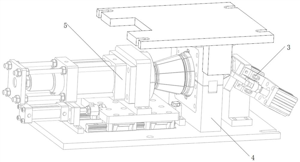
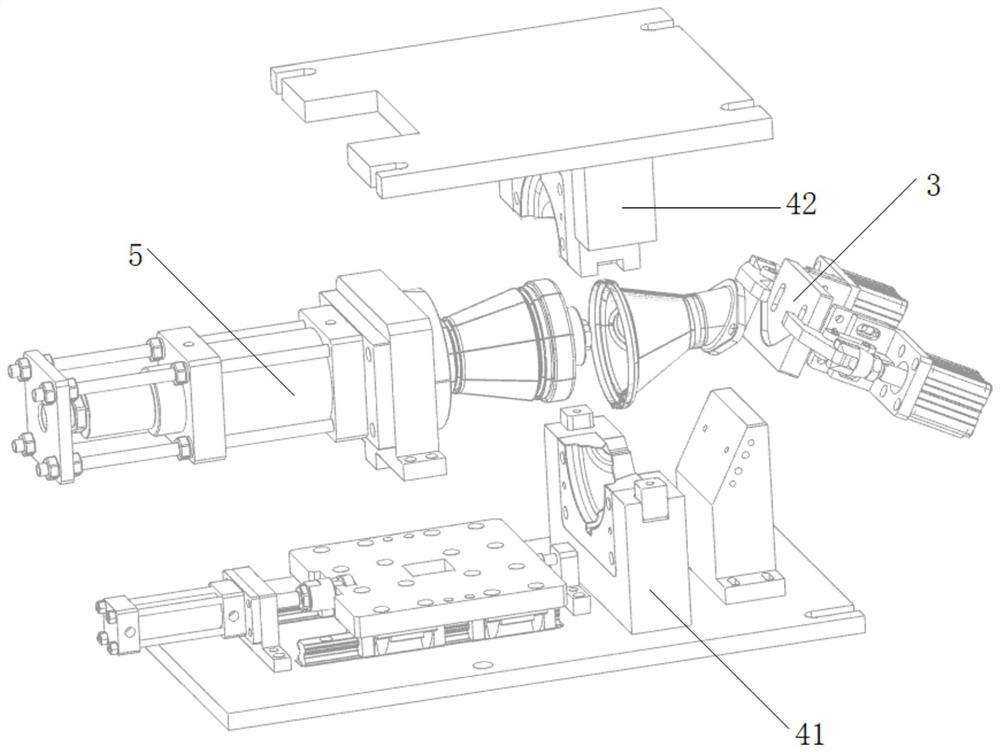
The invention discloses cone assembly shaping equipment which comprises a positioning mechanism, a shaping mechanism and a forming mechanism which are arranged on the same base. The positioning mechanism is used for positioning the flange end of a cone component; the shaping mechanism is used for externally expanding and shaping a taper pipe of the fixed cone component; and when the shaping mechanism expands and shapes the taper pipe, the forming mechanism extrudes and forms the end part of the taper pipe of the cone component. After a product is fixed by the positioning mechanism, the forming mechanism wraps the outer side of the product, a large end opening of the product is restrained to be round through a cavity of the forming mechanism, in order to prevent the product from rebounding after the forming mechanism unloads force, the shaping mechanism expands outwards from the inner side of the product to form extrusion, and the three parts are combined to complete forming of the product at a time, so that the purpose of rounding is achieved.

Description

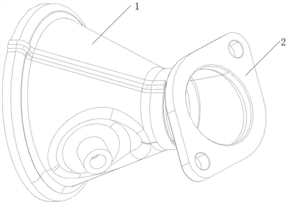
technical field [0001] The invention relates to cone welding equipment, in particular to a cone component shaping equipment. Background technique [0002] The intake end cone assembly of the automobile engine exhaust system comprises a cone pipe 1 and a flange connection pipe 2 connected thereto (such as figure 1 ). When the existing cone components are welded, large deformation will occur due to heating, which will affect the product accuracy. Therefore, in the industry, the welded products need to be reshaped, otherwise the tolerance requirements of production will not be met; but the existing technologies are basically Artificial shaping is adopted, and the efficiency of artificial shaping is low, and the shaping effect is poor. [0003] In addition, there are also ordinary shaping molds for shaping. Generally, the product is shaped by multi-directional positioning and / or multi-process. During ordinary shaping, first, the product undergoes elastic deformation during sha...

Claims


Application Information

Patent Timeline
IPC IPC(8): B21D3/16B21D43/00B21D37/10B21D53/88
CPCB21D3/16B21D43/003B21D37/10B21D53/88
Inventor 谢潮扬陈期平
Owner 重庆爱驰威汽车零部件有限公司
Learn More