Machining device and machining process of motor stator punching sheet

A technology for processing devices and motor stators, applied in positioning devices, feeding devices, storage devices, etc., can solve the problems of increased use cost, difficult operation, high heat loss, etc. small area effect

Pending Publication Date: 2022-01-28
台州市华熠冲件有限公司
View PDF0 Cites 4 Cited by
  • Summary
  • Abstract
  • Description
  • Claims
  • Application Information

AI Technical Summary

Problems solved by technology

[0004] The purpose of the present invention is to solve the complex structure, bulky size, difficult operation, and many electronic control devices in the prior art, high heat loss caused by long-term operation, increased energy consumption, and increased use costs. Complex structure, many electronic control devices lead to difficult maintenance and high cost in the later stage, and a processing device and processing technology for motor stator punching are proposed

Method used


Image

  • Machining device and machining process of motor stator punching sheet
  • Machining device and machining process of motor stator punching sheet
  • Machining device and machining process of motor stator punching sheet

Examples


Embodiment 1

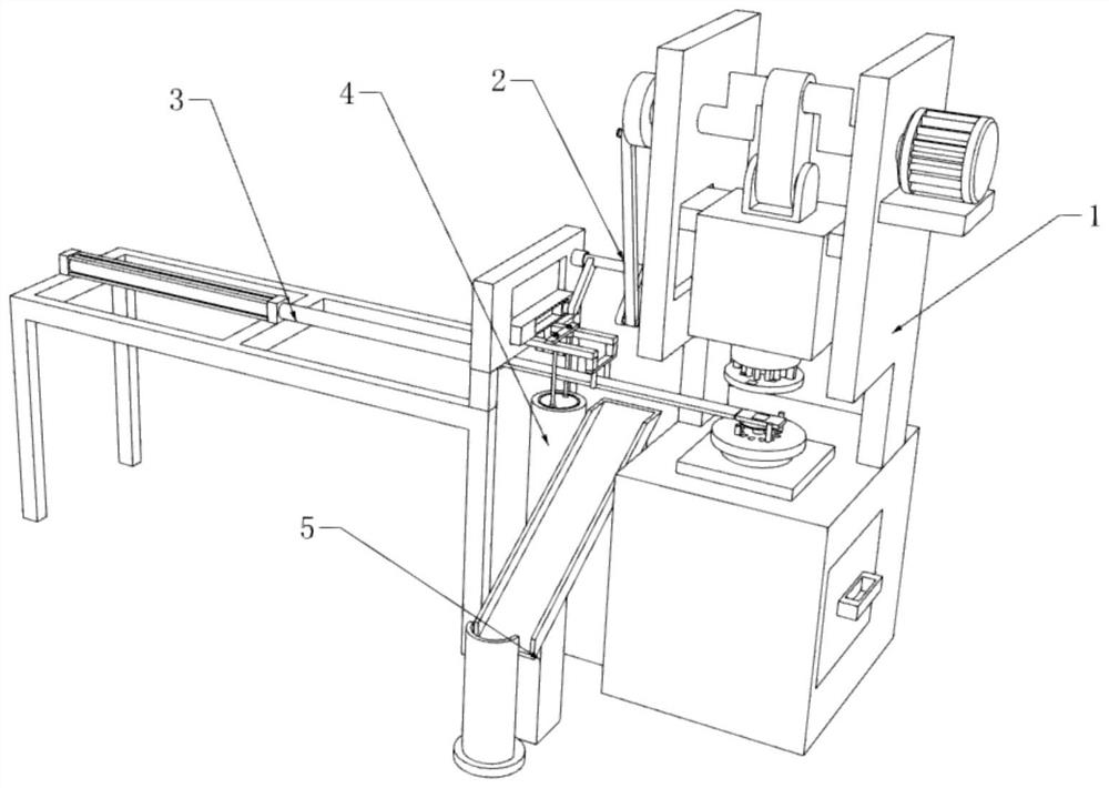
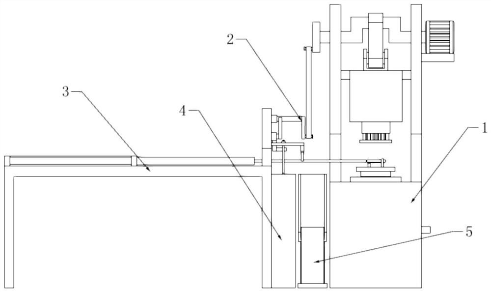
[0040] refer to figure 1 and 2 , a processing device and processing technology for motor stator punching, including a punching machine, a feeding mechanism 3, a linkage mechanism 2 and a material storage mechanism 4, the punching machine is connected to the feeding mechanism 3 through a communication mechanism 2, and the feeding mechanism 3 Send the stamping raw materials in the storage mechanism 4 to the stamping machine station for stamping to make stator punching sheets;

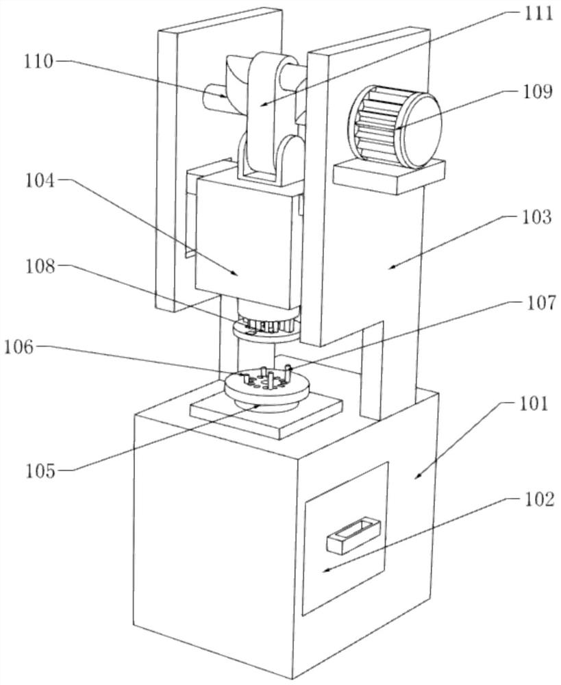
[0041] refer to image 3 and 4, the stamping machine table includes a support platform 101, a support arm 103, a stamping seat 105, a stamping machine body 104, a stamping head 108, a transmission crankshaft 110, a connecting rod 111 and a drive assembly 109, and the interior of the support platform 101 is a hollow structure, and the central control A waste material collection box 102 is provided in the structure, and the support platform 101 is located above the waste material collection box 102 and a...

Embodiment 2

[0064] refer to figure 1 and 8 The difference between this embodiment and the first embodiment is that a stacking mechanism 5 is added, and the stacking mechanism 5 includes a blanking slide 501, a stacking base 504, a material stopper 503, a guide column 502, and a guide column 502. It is fixedly installed at the center of the stacking base 504, and the baffle plate 503 is fixedly mounted on the edge of one side of the stacking base 504. The stacking base 504 is located at the lower end of the blanking slide 501, and the higher end of the blanking slide 501 One end is located directly below the blocking block 215 .

[0065] The stamped stator punches are forced to disengage after passing through the blocking block 215, fall into the lower blanking slide 501 and slide to the stacking base 504, and pass through the blocking of the blocking plate 503, the center hole of the stator punches is sleeved on the guide column 502 And finally fall on the stacking base 504, and each su...


PUM


Abstract

The invention discloses a machining device and a machining process of a motor stator punching sheet, relates to the field of motor stators, and aims to solve the problems that an existing machining device is complex in structure, large in size, high in operation difficulty, large in number of electric control devices, high in heat energy loss caused by long-term operation, high in energy consumption, and high in use cost. Due to the complex structure, in order to solve the problems of high later maintenance difficulty and high cost caused by many electric control devices, the invention provides the following scheme: the machining device comprises a punching machine table, a feeding mechanism, a linkage mechanism and a storage mechanism, and the punching machine table is in transmission connection with the feeding mechanism through the linkage mechanism; and the feeding mechanism is used for feeding the punching raw material in the storage mechanism to the punching machine table for punching to form a stator punching sheet. The device is compact in structure and small in occupied area, the number of structural parts of the device is reduced, energy consumption is reduced, all functional parts act synchronously, the actions of feeding, returning and collecting can be completed within extreme time, and the working efficiency of the device is greatly improved.

Description

technical field [0001] The invention relates to the field of motor stators, in particular to a processing device for stamping a motor stator and a processing technology thereof. Background technique [0002] The stator core is an important part of the stator and the main component of the motor magnetic circuit. It is composed of fan-shaped piece, ventilation groove piece, positioning rib, upper and lower tooth pressure plate, tension bolt and supporting plate and other parts. The stator core is made of silicon steel sheets punched into fan-shaped pieces and stacked on the positioning ribs. The positioning ribs are welded to the frame ring plate through the supporting plate, and the core is compressed into a whole through the upper and lower tooth pressure plates with tension bolts. The iron core is also the part where the winding is placed. When the generator is running, the iron core will be subjected to the combined effects of mechanical force, thermal stress and electrom...

Claims


Application Information

Patent Timeline
Patent Type & Authority Applications(China)
IPC IPC(8): B21D28/02B21D43/18B21D43/22B21D43/24B21D45/00B21D45/04
CPCB21D28/02B21D43/18B21D43/22B21D43/24B21D45/003B21D45/04
Inventor 朱浩文
Owner 台州市华熠冲件有限公司
Why Eureka
Try Eureka