
Magnetron sputtering target capable of improving utilization rate of target material

A magnetron sputtering and utilization technology, which is applied in the field of magnetron sputtering targets, can solve the problems of serious etching degree and low utilization rate of target materials, so as to improve the utilization rate, improve the sputtering etching ability, and improve the sputtering efficiency. The effect of firing rate

Inactive Publication Date: 2022-01-28
苏州德耐纳米科技有限公司
View PDF0 Cites 0 Cited by
  • Summary
  • Abstract
  • Description
  • Claims
  • Application Information

AI Technical Summary

Problems solved by technology

[0004] The purpose of the present invention is to provide a magnetron sputtering target that can improve the utilization rate of the target, so as to solve the problem of etching in the region with a strong magnetic field in the middle of the target during the use of the existing target proposed in the above background technology. The degree is more serious than the surrounding area, which leads to the problem of low target utilization

Method used


Image

  • Magnetron sputtering target capable of improving utilization rate of target material
  • Magnetron sputtering target capable of improving utilization rate of target material
  • Magnetron sputtering target capable of improving utilization rate of target material

Examples


Embodiment Construction

[0027] The following will clearly and completely describe the technical solutions in the embodiments of the present invention with reference to the accompanying drawings in the embodiments of the present invention. Obviously, the described embodiments are only some, not all, embodiments of the present invention.

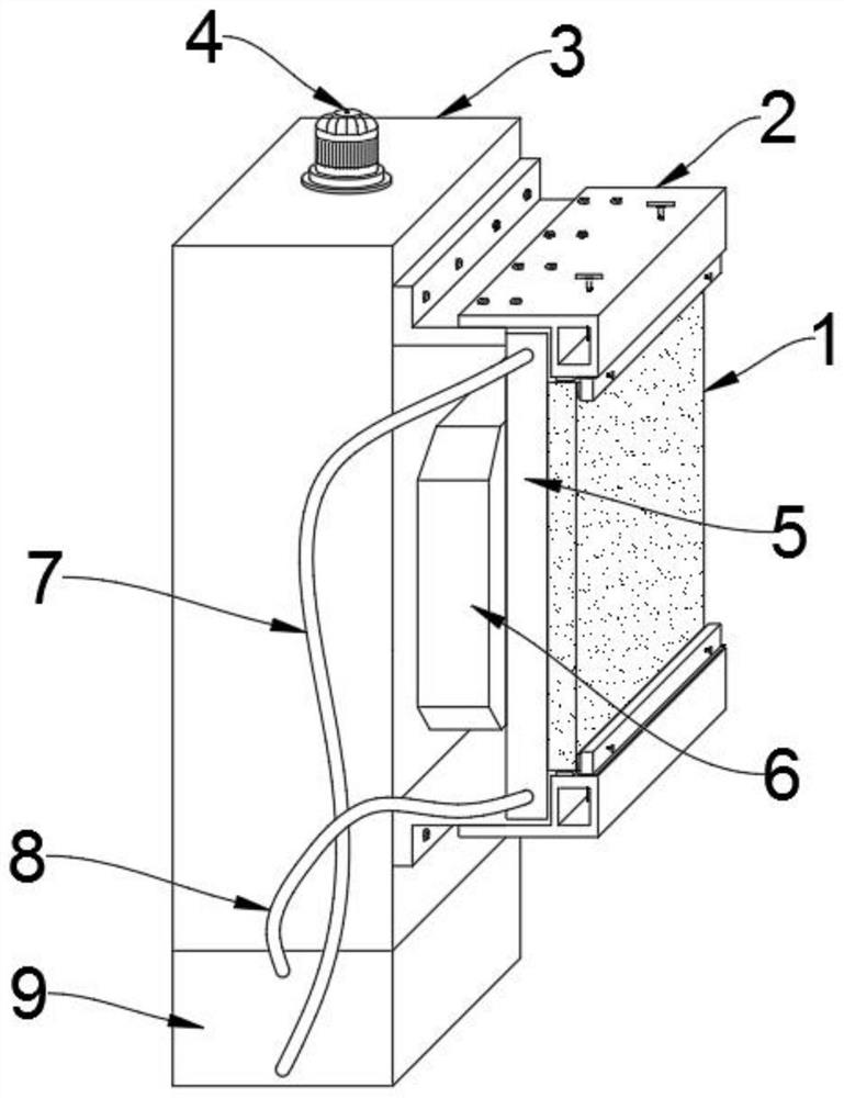
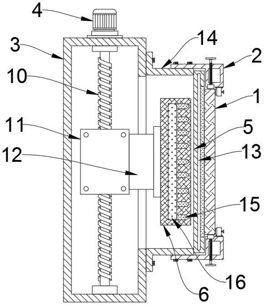
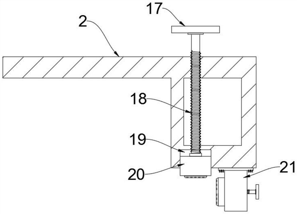
[0028] see Figure 1-8, an embodiment provided by the present invention: a magnetron sputtering target that can improve the utilization rate of the target, including a target 1, a fixing frame 2 is provided above and below the target 1, and the fixing frame 2 is installed below There is a second pressure box 21, and the fixed frame 2 and the second pressure box 21 are fixedly connected by bolts. The inside of the fixed frame 2 is provided with a pressure chamber 19, and the top of the fixed frame 2 is provided with a first rotating rod 17. The first screw rod 18 is installed below the rod 17, and the first rotating rod 17 is fixedly connected with the first screw rod...


PUM


Abstract

The invention discloses a magnetron sputtering target capable of improving the utilization rate of a target material, relates to the technical field of magnetron sputtering, and aims to solve the problem that the utilization rate of the target material is low due to the fact that the etching degree of an area with a strong magnetic field in the middle of the target material is higher than that of the surrounding area in the using process of the existing target material in the prior art. A cooling back plate is arranged on one side of the target material, a fixing base is arranged on one side of the cooling back plate, a magnetic block is arranged in the fixing base, a magnetic core is installed on one side of the magnetic block, the magnetic block is fixedly connected with the magnetic core, and fixing plates are arranged above and below the fixing base correspondingly. The fixing plates are fixedly connected with the cooling back plate through bolts, a power box is installed on one sides of the fixing plates, the fixing plates are fixedly connected with the power box through bolts, a ball screw is installed in the power box, the power box is rotationally connected with the ball screw, and a lifting block is installed on the outer side of the ball screw. The ball screw is in sliding connection with the lifting block through a ball.

Description

technical field [0001] The invention relates to the technical field of magnetron sputtering, in particular to a magnetron sputtering target which can improve the utilization rate of the target. Background technique [0002] With the continuous development of society and the continuous improvement of various technologies, magnetron sputtering is a kind of physical vapor deposition, which has the advantages of simple equipment, easy control, large coating area and strong adhesion. The principle of magnetron sputtering is that incident particles In the collision process with the target, the incident particle undergoes a complex scattering process in the target, collides with the target atom, and transfers part of the momentum to the target atom, and the target atom collides with other target atoms to form a cascade process. During the process, some target atoms near the surface gain enough momentum to move outwards, leaving the target and being sputtered out. At present, magnet...

Claims


Application Information

Patent Timeline
Patent Type & Authority Applications(China)
IPC IPC(8): C23C14/35
CPCC23C14/3407C23C14/35
Inventor 范玉山张梓江
Owner 苏州德耐纳米科技有限公司
Learn More