Bending-dominated pressure spring type lattice structure
Active Publication Date: 2022-01-28
NANJING UNIV OF SCI & TECH
View PDF4 Cites 0 Cited by
Summary
Abstract
Description
Claims
Application Information
AI Technical Summary
This helps you quickly interpret patents by identifying the three key elements:
Problems solved by technology
Method used
Benefits of technology
Problems solved by technology
[0004]
The purpose of the present invention is to provide a composite lattice structure periodically arranged, by imitating the tibia and combining the shock-absorbing characteristics of the helical structure, a periodic composite structure with good compression performance and shock-absorbing energy-absorbing characteristics is formed to solve the current problem It is difficult to take into account the strength and shock absorbing properties of the lattice structure at the same time
Method used
Image
Click on the blue label to locate the original text in one second.
Reading with bidirectional positioning of images and text.
Examples
Embodiment 1
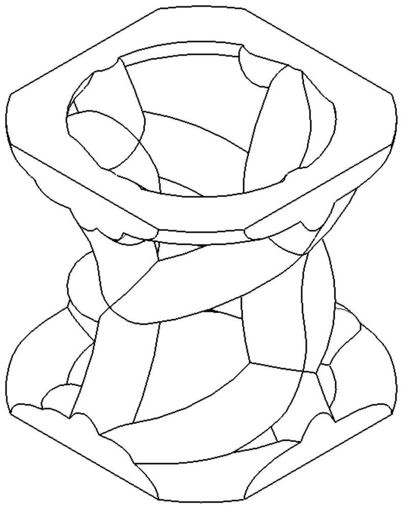
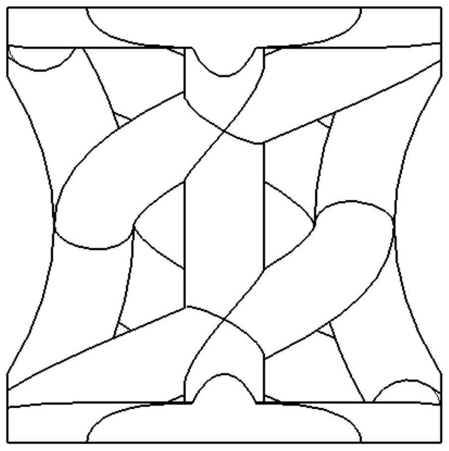
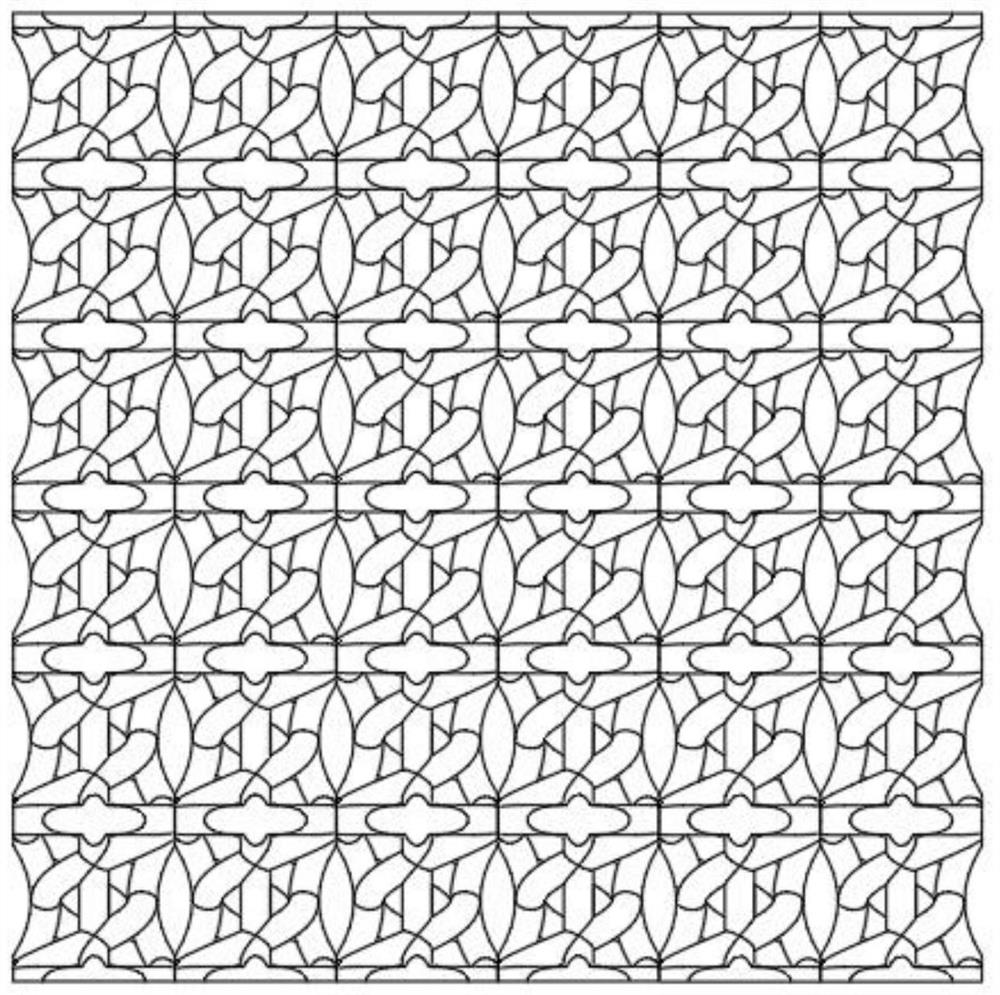
[0049] Example 1: Two-concuffing single cells and dot matrix structures
[0050] like figure 1 , figure 2 As shown: Each point of the cell is included in four curved support rods, two spiral links. The detailed implementation process is as follows: Using the three-dimensional modelingsoftware CATIA V5, on the square of 5mm × 5mm × 5mm square, it is parallel to the four sides of the XOY plane (such as points (2.5, 0, 0), (2.5, 0, 5)) The circle having a diameter of 5 mm is established on both planes.
[0051] Create a point (1.5, 0, 0.5), then curve three points (2.5, 0, 5), (1.5, 0, 2.5), and connect the curved support rod, which can be obtained. Also bent rod. With the contour of the curved support, the point (2.5, 0, 0) is the starting point, the extension shaft is the z-axis, the pitch is 5mm, the direction is counterclockwise, establishes a spiral rod, and other spiral rods are used.
[0052] Different cross-sectional treatments for different relative densities, the cross-sec...
Embodiment 2
[0055] Example 2: Two-concuffing cell optimization treatment:
[0056] Import the two plunge cell structure into the Abaqus software for compression experimental simulation analysis, resulting in a stress distribution map, such as Figure 4 As shown, the stress distribution cloud map is compressed to 16%, as shown in the figure, the stress is mainly distributed on the curved support bar, and the two spiral support rods are less responsive, resulting in uneven stress distribution, for the cell and It has a big impact on the compression performance of the dot matrix.
[0057] Analysis of the interposed cloud map of two plunge cells, mainly optimized the spiral support rod: increase the pitch, increased to 20 mm, which is 20mm, while increasing the number of spiral connectors is 4 Root, making the cell structural stress distribution more uniform, and at the same time reduce the curved support lever curve to a certain extent, the stress distribution cloud Figure 8 Indicated.
Embodiment 3
[0058] Example 3: Tetractive spring type single cells and dot matrix structure
[0059] like Figure 5 , Image 6 As shown: Each point of the cell element includes four arcuate support rods, four spiral links. The detailed implementation process is as follows: Use three-dimensional modelingsoftware CATIAV5, in parallel at the middle of the XOY planes in each of the four sides of the XOY plane, (2.5, 0, 5)) At the same time, a circle having a diameter of 5 mm is established on both planes.
[0060] Create a point (1.5, 0, 0.5), and the curve connection is performed on three points (2.5, 0, 5), (1.7, 0, 2.5) to obtain an arcuate support rod to make it curved The support rod is reduced relative to the two plunge cell radians, and the other curved support rod can be obtained. With the contour of the curved support, the point (2.5, 0, 0) is the starting point, the extension shaft is a z-axis, the pitch is 20 mm, and the direction is counterclockwise, establishes a spiral rod, and the ot...
PUM
Abstract
The invention discloses a bending-dominated pressure spring type lattice structure. The structure a plurality of dot matrixcell elements, and each dot matrixcell element is of a central symmetry structure and comprises an upper circular ring, a lower circular ring, an arc-shaped supporting rod and a spiral connecting rod; the upper end of each arc-shaped supporting rod is connected with the upper circular ring, the lower end of each arc-shaped supporting rod is connected with the lower circular ring, and the arc-shaped supporting rods are evenly arranged between the upper circular ring and the lower circular ring; the starting point and the ending point of the spiral connecting rod are intersection points of a certain arc-shaped supporting rod, the upper circular ring and the lower circular ring, the spiral direction of the spiral connecting rod is anticlockwise, the spiral connecting rod takes the arc-shaped supporting rod as the outline, the whole spiral connecting rod is in a middle concave shape, and the spiral connecting rod is evenly distributed between the upper circular ring and the lower circular ring. When a load is borne, the arc-shaped supporting rods play a role in bearing, the spiral connecting rods play a role in supporting and buffering, the load is fully absorbed and borne, and compared with a traditional cell element structure, stress distribution is higher in bearing performance, has more excellent mechanical performance and has more advantages in modulus, strength and energy absorption.
Description
Technical field [0001] The present invention belongs to the field of material structure, and more particularly to a bending dominant rings-type dot array structure. Background technique [0002] Applying porous structures is currently recognized as an engineering program, which can improve the mechanical performance and other mechanical properties. It is used in aerospace and aviation industries. It is calculated that the aircraft will be used to change the aircraft, in the same performance Under conditions, the aircraft will be reduced to half of the original. Another important mechanical properties to apply porous structures are improving impacttoughness, and the application can effectively reduce trauma of passengers in the automotive accident. [0003] The dot matrix structure is a kind of porous material and the structure, and is also referred to as a lattice structure. This type of structure often presents a porous, periodic, arrayable distribution, with high quality mecha...
Claims
Application Information
Patent Timeline
Application Date:The date an application was filed.
Publication Date:The date a patent or application was officially published.
First Publication Date:The earliest publication date of a patent with the same application number.
Issue Date:Publication date of the patent grant document.
PCT Entry Date:The Entry date of PCT National Phase.
Estimated Expiry Date:The statutory expiry date of a patent right according to the Patent Law, and it is the longest term of protection that the patent right can achieve without the termination of the patent right due to other reasons(Term extension factor has been taken into account ).
Invalid Date:Actual expiry date is based on effective date or publication date of legal transaction data of invalid patent.

