Check patentability & draft patents in minutes with Patsnap Eureka AI!

Crystallizer with separation and collapse prevention functions

A crystallizer and functional technology, applied in the field of solid particle crystallization, can solve the problems of small application range and poor purification effect, and achieve the effect of inconvenient purification

Pending Publication Date: 2022-02-08
宣城镐渭工业技术有限公司
View PDF0 Cites 0 Cited by
  • Summary
  • Abstract
  • Description
  • Claims
  • Application Information

AI Technical Summary

Problems solved by technology

[0003] The purpose of the present invention is to provide a crystallizer with separation and anti-collapse functions, so as to solve the problems of small scope of application and poor purification effect in the above-mentioned background technology

Method used


Image

  • Crystallizer with separation and collapse prevention functions
  • Crystallizer with separation and collapse prevention functions
  • Crystallizer with separation and collapse prevention functions

Examples


Embodiment 1

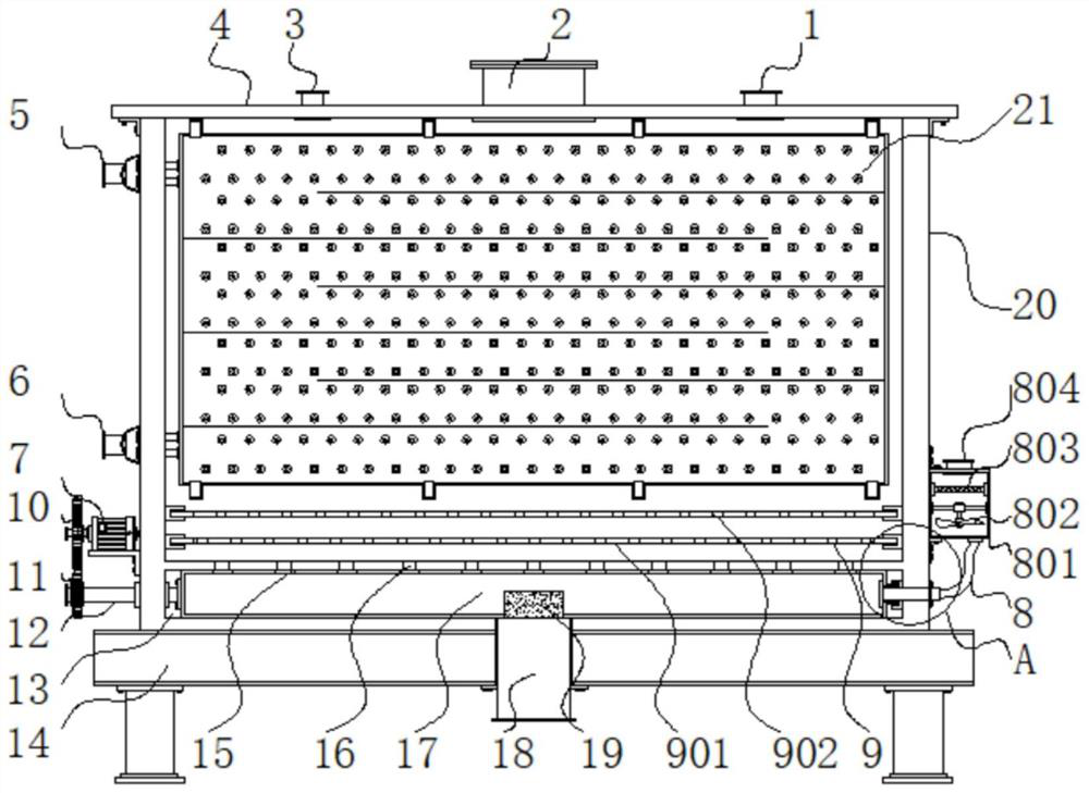
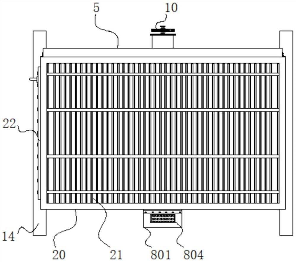
[0021] Example 1: See Figure 1-5 An isolated and anti-collapse function having a crystallizer, comprising a chassis 14, the chassis 14 is mounted to the top case 20, and a position at a center of the inside bottom of the housing 20 defines a cavity 13, 13 is provided with an internal cavity the bottom end of the feed tube 17, and the center position of the lower surface of the feed tube 17 defines a notch 19, at a central position of the bottom end of the inner cavity 13 is provided with a discharge tube 18 and outlet tube 18 extends to the base below 14, the upper surface of the lower feed tube 17 defines a plurality of grooves 15 first holes, and even the bottom inside of the cabinet 20 defines a groove 16 of the second hole, the first hole 15 and a slot 16 a second slot holes a correspondence, and the first groove hole slightly larger than the aperture of the second aperture 15 of the aperture 16 of the groove, the lower side of the feed tube 17 is connected to the pawl 12 and ...

Embodiment 2

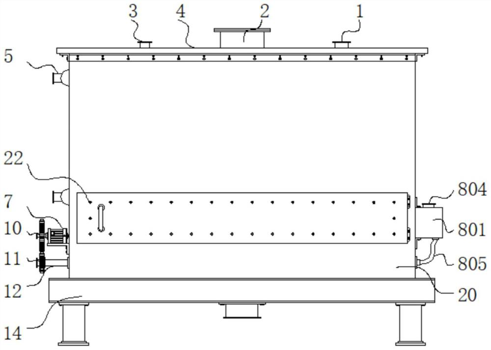
[0027] Example 2: Drying oven 801 comprises a structure 8, blower 802, air filter 803, air inlet 804, the hose 805 and the communication pipe 806, communication pipe 806 is fixed to the lower side of the housing 20, and the oven settings 801 on the box body side communication pipe 80620, oven 801 provided with a top air inlet 804, and 801 inside the oven air filter 803 is mounted transversely, the oven interior 801 below the air filter 803 is mounted with a transverse fan 802, and the bottom side 801 of the hose 805 is connected to the oven;

[0028] One end of the communication pipe 806 through the feed box 20 and the lower side of the tube 17 extends to the interior of the cutting tube 17, and the bottom end of the hose 805 is connected to the communicating pipe 806;

[0029] Diameter drive gear 10 is larger than the diameter of the driven gear 11 and the driven gear 11 and drive gear 10 are connected by a rodent;

[0030] Specifically, such as figure 1 , figure 2 , image 3 and ...


PUM


Abstract

The invention discloses a crystallizer with separation and collapse prevention functions, and relates to the technical field of solid particle crystallization. The crystallizer with separation and collapse prevention functions comprises a base, wherein a box body is installed at the top end of the base, a cavity is formed in the center of the inner portion of the bottom end of the box body, a feeding pipe is arranged in the cavity, a groove opening is formed in the center of the lower surface of the feeding pipe, a discharging pipe is arranged in the center of the bottom end in the cavity, the bottom end of the discharging pipe extends to the position below the base, a plurality of first hole grooves are formed in the upper surface of the discharging pipe, second hole grooves are evenly formed in the bottom end in the box body, the first hole grooves and the second hole grooves are in one-to-one correspondence, and the hole diameter of the first hole grooves is slightly larger than that of the second hole grooves. By arranging a first sieve plate 901 and a second sieve plate 902, materials can be prevented from sliding down along with impurities, the materials are prevented from being discharged along with the impurities, and the structure is beneficial to improving the applicability of the device.

Description

Technical field [0001] Technical Field The present invention relates to solid crystalline particles, in particular to a crystallizer having a separation and anti-collapsing function. Background technique [0002] Mold is a crystalline solid material purification equipment, along with the continuous development and progress in the field of chemical and medical our country, there are many deficiencies in terms of the production of solid material, wherein the purity of the material is one of the most important one, which affects the quality of the material production, particularly in the medical field, fine particles of the drug purity of the drug will play a decisive role, purity is not high, the drug may affect the treatment effect, when severe, more patients will cause secondary damage, and conventional crystallizer many deficiencies, such as centrifugation method, depending on the material density of the material using the centrifuge was centrifuged, but this method is only appl...

Claims


Application Information

Patent Timeline
Patent Type & Authority Applications(China)
IPC IPC(8): B01D9/02B01D1/00B01D29/03B01D29/56B01D29/96B01D46/10
CPCB01D29/03B01D29/56B01D29/96B01D9/0063B01D46/10B01D1/0041
Inventor 徐勇张厚清伍照全方觉舒何浩李亚黄一鸣
Owner 宣城镐渭工业技术有限公司
Features
  • R&D
  • Intellectual Property
  • Life Sciences
  • Materials
  • Tech Scout
  • Unparalleled Data Quality
  • Higher Quality Content
  • 60% Fewer Hallucinations
Learn More