Power chamber positioning mechanism for hydrogen fuel cell pure electric passenger car

A pure electric passenger car and fuel cell technology, which is applied in the direction of electric power unit, layout combined with internal combustion engine fuel supply, power unit, etc. The effect of cluttered lines and neat lines

Pending Publication Date: 2022-02-08
ANHUI ANKAI AUTOMOBILE
View PDF0 Cites 1 Cited by
  • Summary
  • Abstract
  • Description
  • Claims
  • Application Information

AI Technical Summary

Problems solved by technology

Therefore, a fuel cell pure electric bus with a hydrogen supply system has emerged as the times require, but in the prior art, the fuel cell pure electric bus with a hydrogen supply system is inconvenient to install the hydrogen supply system, fuel cell system and electrical system in the power room, and has greater limitations

Method used


Image

  • Power chamber positioning mechanism for hydrogen fuel cell pure electric passenger car
  • Power chamber positioning mechanism for hydrogen fuel cell pure electric passenger car
  • Power chamber positioning mechanism for hydrogen fuel cell pure electric passenger car

Examples


Embodiment 1

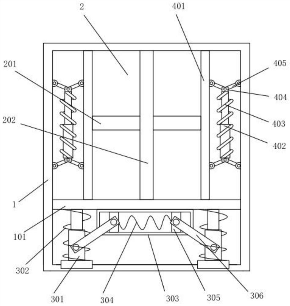
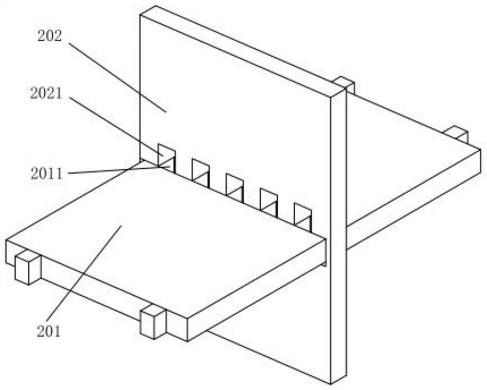
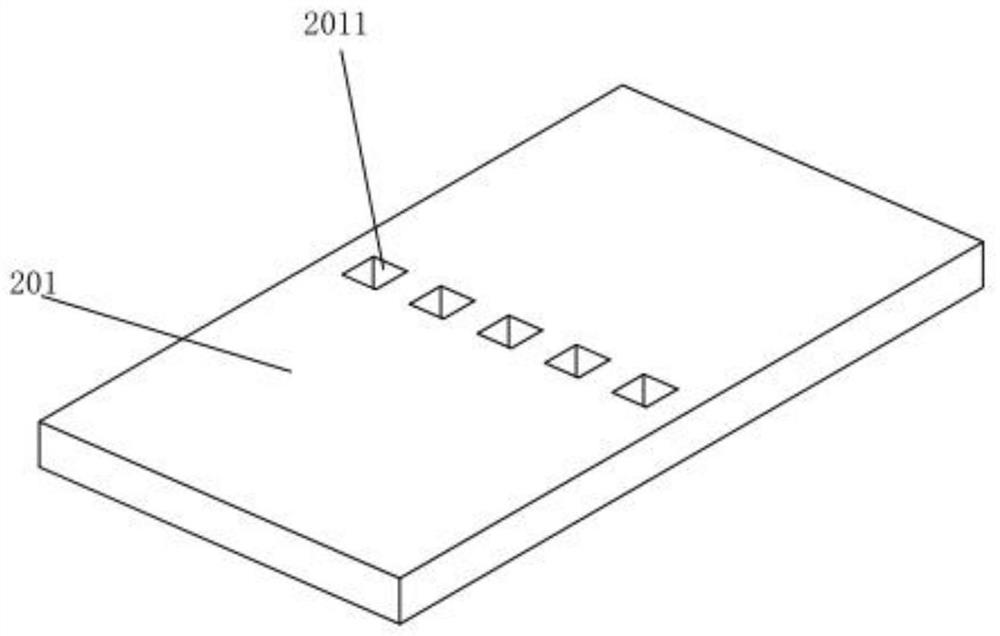
[0038] see figure 1 As shown, the present invention is a power room positioning mechanism for a hydrogen fuel cell pure electric bus. The positioning plate 101 inside the positioning platform 1 is provided with an erection mechanism 2. The erection mechanism 2 is composed of a horizontal platen 201 and a vertical platen. 202 cross mortise and tenon structure, the erection mechanism 2 forms a multi-cavity structure between the interior of the positioning platform 1 and the positioning plate 101, and the multi-cavity structure of the positioning platform 1 is used for hydrogen supply systems, fuel cell systems and electrical systems. Install;

[0039] The positioning platform 1 is a box-type cavity structure. When in use, a plurality of cavity structures are formed between the cross structure formed by the horizontal platform 201 and the vertical platform 202 and the positioning plate 101, and a supply space is formed inside each cavity. The installation area of ​​hydrogen syst...

Embodiment 2

[0045] refer to figure 1 , the implementation of this embodiment is basically the same as that of Embodiment 1, the difference is that the bottom of the positioning plate 101 is provided with a vertical buffer mechanism for the erection mechanism 2, and both sides of the plate surface of the positioning plate 101 are provided with buffers for the erection mechanism 2. Horizontal buffer mechanism;

[0046] When in use, the buffer protection of the erection mechanism 2 during the operation of the electric vehicle is realized through the vertical buffer mechanism on the bottom surface of the positioning plate 101 and the lateral buffer mechanisms on both sides, so as to realize synchronous protection of the equipment in the entire power room and effectively improve the performance of the power room. The erection stability of the equipment.

[0047]Wherein, the vertical buffer mechanism includes a quadrangular frame 303 fixedly arranged on the bottom surface of the positioning pl...

Embodiment 3

[0056] refer to figure 1 , Figure 5 , the implementation of this embodiment is basically the same as that of Embodiment 2, the difference is that auxiliary plates 2012 are provided on both sides of the transverse platen 201, and the side longitudinal sides of the auxiliary plate 2012 are provided with notches suitable for the transverse limit plate 401. The equipped slider, that is, by adding an auxiliary plate 2012, further improves the movement stability of the erection mechanism 2 in the vertical direction. Mechanism 2 is more stable in force in the horizontal direction, improving the stability of lateral buffering.


PUM


Abstract

The invention discloses a power chamber positioning mechanism for a hydrogen fuel cell pure electric passenger car, the power chamber positioning mechanism for the hydrogen fuel cell pure electric passenger car comprises a positioning rack, an erecting mechanism is arranged in the positioning rack, the erecting mechanism is formed by a transverse platen and a vertical platen in a crisscross mortise and tenon joint mode, the erecting mechanism forms a multi-cavity structure between the interior of the positioning rack and the positioning plate, so that the multiple independent cavity structures can adapt to distribution and installation of equipment such as a hydrogen supply system, a fuel cell system and an electrical system in the power chamber, and the erecting mechanism is arranged on the positioning plate. Buffering protection of the erecting mechanism in the running process of the electric vehicle is achieved through the vertical buffering mechanism on the bottom face of the positioning plate and the transverse buffering mechanisms on the two sides, so that synchronous protection of equipment in the whole power chamber is achieved, and the erecting stability of the equipment in the power chamber is effectively improved.

Description

technical field [0001] The invention relates to the technical field of hydrogen fuel electric buses, in particular to a power chamber positioning mechanism for hydrogen fuel cell pure electric buses. Background technique [0002] How to do a good job in carbon peaking and carbon neutrality is an environmental issue of concern to all sectors of society. As the third industry that contributes to emissions, the automobile industry needs to be one step ahead. Low-carbonization and electrification are the major trends of green and sustainable development in the global energy and transportation fields. [0003] Against the background of intensified changes in automobile cleanliness and intelligence, and the reshaping of the global automobile industry structure, my country has proposed a "three-vertical" strategy for the comprehensive development of fuel cell vehicles, hybrid electric vehicles, and pure electric vehicles. Among them, hydrogen fuel cell vehicles are relatively Compa...

Claims


Application Information

Patent Timeline
Patent Type & Authority Applications(China)
IPC IPC(8): B60K1/04B60K15/07B60R16/02F16F15/067
CPCB60K1/04B60K15/07B60R16/02B60R16/0215F16F15/067F16F2230/0023
Inventor 尹婉李静鲁飞陈炜
Owner ANHUI ANKAI AUTOMOBILE
Why Eureka
Try Eureka