Supercharge Your Innovation With Domain-Expert AI Agents!

Method, equipment and medium for controlling evaporation of waste liquid heat pump

A technology for heat pump evaporation and control equipment, applied in chemical instruments and methods, heating water/sewage treatment, special treatment targets, etc., can solve problems such as low efficiency, low degree of automation, equipment damage, etc.

Pending Publication Date: 2022-02-08
718TH RES INST OF CHINA SHIPBUILDING INDAL CORP
View PDF5 Cites 0 Cited by
  • Summary
  • Abstract
  • Description
  • Claims
  • Application Information

AI Technical Summary

Problems solved by technology

[0003] At present, the automatic control and operation of domestic waste liquid heat pump evaporation treatment technology is still in the initial research stage. The control system and function of waste liquid heat pump evaporation are not perfect, and the degree of automation is not high. It needs to rely on manual operation and experience judgment, and the efficiency is low. , time-consuming, and bring great inconvenience to the operator
Especially when the heat pump evaporation device has an abnormal working condition, relying on humans to judge the abnormal situation and carry out corresponding processing, the cost of emergency response and processing is high, not timely enough, and it is easy to cause errors due to human factors, resulting in unqualified products, equipment damage, The device shuts down, and even causes serious losses such as waste liquid leakage
[0004] In summary, the traditional solution for controlling the evaporation of waste liquid heat pumps has the disadvantages of low degree of automation, poor operation safety, reliability and stability

Method used

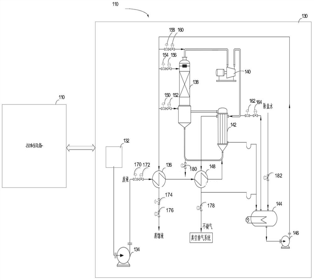
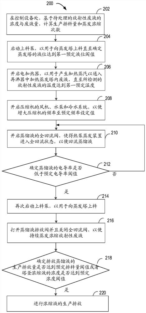
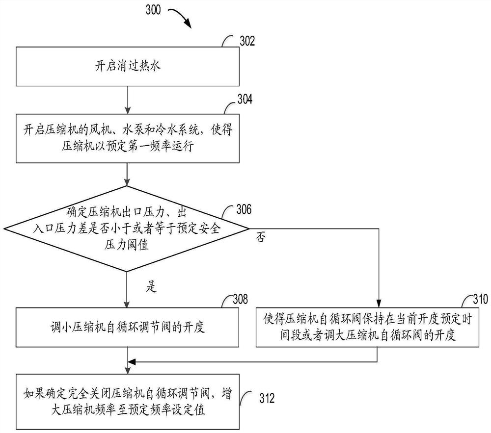

Image

  • Method, equipment and medium for controlling evaporation of waste liquid heat pump
  • Method, equipment and medium for controlling evaporation of waste liquid heat pump
  • Method, equipment and medium for controlling evaporation of waste liquid heat pump

Examples


Embodiment Construction

[0031]Preferred embodiments of the present disclosure will be described in more detail below with reference to the accompanying drawings. Although preferred embodiments of the present disclosure are shown in the drawings, it should be understood that the present disclosure can be embodied in various forms and should not be limited to the embodiments set forth herein. Rather, these embodiments are provided so that this disclosure will be thorough and complete, and will fully convey the scope of the disclosure to those skilled in the art.

[0032] As used herein, the term "comprise" and its variants mean open inclusion, ie "including but not limited to". The term "or" means "and / or" unless otherwise stated. The term "based on" means "based at least in part on". The terms "one example embodiment" and "one embodiment" mean "at least one example embodiment." The term "another embodiment" means "at least one further embodiment". The terms "first", "second", etc. may refer to dif...


PUM


Abstract

The invention relates to a method, equipment and a medium for controlling evaporation of a waste liquid heat pump. The method comprises the following steps: calculating the production discharge amount and the evaporation concentration frequency based on the concentration and the waste liquid amount of to-be-treated waste liquid; feeding an evaporation tower until the liquid level of the evaporation tower reaches a first preset liquid level threshold value; heating the evaporation tower until the detected temperature of the waste liquid reaches a first preset temperature; increasing the frequency of a compressor to a preset frequency set value; refluxing the distillate; feeding the evaporation tower again in response to determining that the conductivity of the distillate is lower than a preset conductivity threshold value; opening a distillate drain valve and closing a total reflux valve; and in response to determining that the production discharge amount of the distillate reaches the preset discharge amount threshold value or the concentration of the tower kettle concentrated solution reaches the preset concentration threshold value, discharging the concentrated solution. The waste liquid heat pump evaporation process can be automatically controlled, and the safety, reliability and stability of system operation are improved.

Description

technical field [0001] The present disclosure relates generally to heat pump evaporation processing technology, and in particular, to methods, computing devices, and media for controlling waste liquid heat pump evaporation. Background technique [0002] For the heat pump evaporation treatment of flammable, explosive, toxic and harmful waste liquid, in view of the risk of waste liquid leakage, the safety, reliability and operation stability of the technology used to control the heat pump evaporation device are particularly important. [0003] At present, the automatic control and operation of domestic waste liquid heat pump evaporation treatment technology is still in the initial research stage. The control system and function of waste liquid heat pump evaporation are not perfect, and the degree of automation is not high. It needs to rely on manual operation and experience judgment, and the efficiency is low. , Time-consuming, bring great inconvenience to the operator. Espec...

Claims


Application Information

Patent Timeline
Patent Type & Authority Applications(China)
IPC IPC(8): C02F1/04
CPCC02F1/04C02F2301/043C02F2303/10
Inventor 李敏刘佳惠任晓影马艳玲刘金玲王成伟于戈
Owner 718TH RES INST OF CHINA SHIPBUILDING INDAL CORP
Features
  • R&D
  • Intellectual Property
  • Life Sciences
  • Materials
  • Tech Scout
  • Unparalleled Data Quality
  • Higher Quality Content
  • 60% Fewer Hallucinations
Learn More