
Joint calibration method for single-line laser radar and camera

A single-line laser radar and laser radar technology, applied in radio wave measurement systems, image data processing, instruments, etc., can solve the problems of invisible two-dimensional laser radar scanning lines, inability to accurately obtain positions and coordinates, and achieve simple and convenient calculation. , to ensure accuracy, to ensure the effect of accuracy

Pending Publication Date: 2022-02-08
安徽省爱夫卡电子科技有限公司 +1
View PDF0 Cites 0 Cited by
  • Summary
  • Abstract
  • Description
  • Claims
  • Application Information

AI Technical Summary

Problems solved by technology

The two-dimensional lidar scan line is invisible, and the position and coordinates of the corresponding feature points cannot be accurately obtained in the image collected by the camera

Method used


Image

  • Joint calibration method for single-line laser radar and camera
  • Joint calibration method for single-line laser radar and camera
  • Joint calibration method for single-line laser radar and camera

Examples


Embodiment

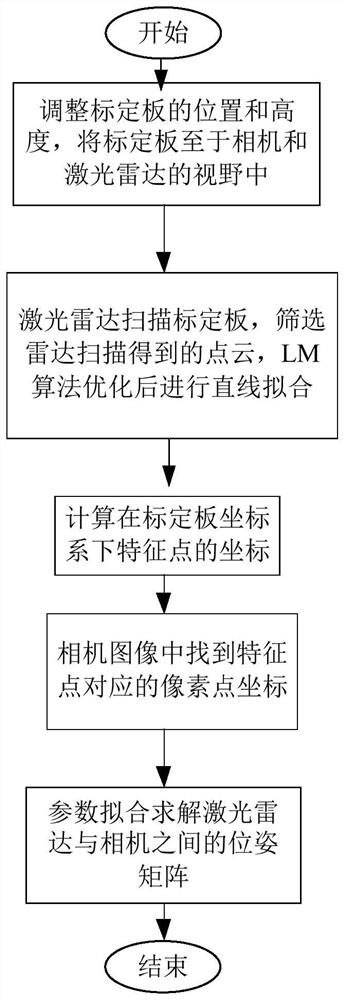
[0045] A single-wire laser radar and camera target joint design and calibration method, comprising the steps of:

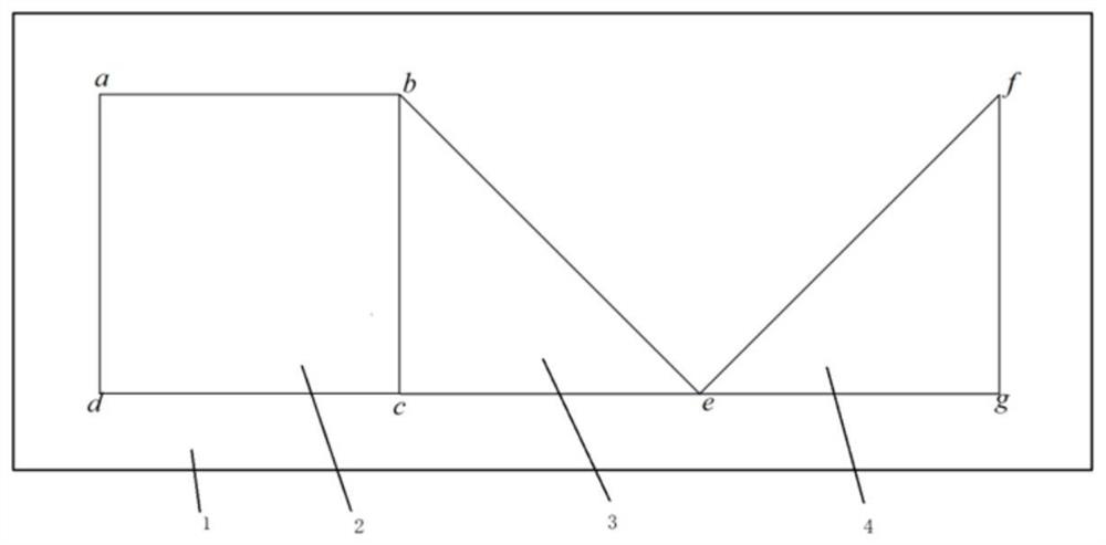
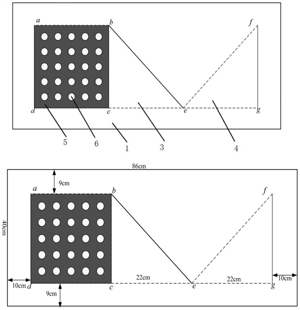
[0046] (1) adjusting the position and height of the calibration plate, the hollow area and a calibration plate with the non-hollow region of the field of view of the camera and the laser radar is placed in;

[0047] (2) a scanning laser radar calibration plate while using the camera to take pictures, a series of a plurality of laser radar scanning point cloud obtained information, the cloud point at the intersection of the boundary line of the hollow and non-hollow area of ​​the scanning lines and the calibration plate as feature points, screening at near point cloud from a number of feature points in the point cloud, the optimization process thereof, by fitting a straight line LM algorithm;

[0048](3) fit equation and the boundary line of the equation by a straight line, the coordinates at the calibration plate coordinate system is calculated;

[0049] (4) find the ...


PUM


Abstract

The invention discloses a joint calibration method for a single-line laser radar and a camera, and belongs to the technical field of multi-sensor calibration. The calibration method comprises the following steps: adjusting the position and height of a calibration plate, and placing the calibration plate with hollowed-out areas and hollowed-out areas in the visual field of a camera and a laser radar; (2) scanning the calibration plate by the laser radar, using a camera for photographing, obtaining a series of point cloud information through scanning of the laser radar, taking point clouds at intersection points of scanning lines and boundary lines of non-hollowed-out areas and hollowed-out areas of the calibration plate as feature points, screening point clouds close to the feature points from a plurality of point clouds, and conducting straight line fitting after optimization processing is conducted on the point clouds through an LM algorithm; (3) calculating coordinates in a coordinate system of the calibration plate through a straight line fitting equation and a boundary line equation; (4) finding out coordinates of pixel points corresponding to the feature points of the laser radar in a camera image; (5) performing parameter fitting to solve a pose matrix between the laser radar and the camera.

Description

Technical field [0001] The present invention relates, to a method for calibrating a joint-line laser radar and the camera for a plurality of sensor calibration technical field, specifically. Background technique [0002] The new technology of artificial intelligence and the combination of the automobile industry began to attract attention and attention. Overall car camera sensor installation can be completed in conjunction with the car's surroundings collected data, analysis and decision-making. But in the harsh environmental conditions, compared with the camera sensors, radar sensors more robust to environmental conditions. Therefore, the combination of lidar and camera is more extensive. Obtain the relationship between the laser radar coordinate system and camera coordinate system is a prerequisite both for data integration. [0003] There are many feature points and is the most common method is simple joint calibration sensor calibration methods. Mainly in the calibration erro...

Claims


Application Information

Patent Timeline
IPC IPC(8): G06T7/80G01S7/497
CPCG06T7/80G01S7/497G06T2207/30204
Inventor 朱志峰代天赐姚勇常雁龙周芳唐得志杨冰倩
Owner 安徽省爱夫卡电子科技有限公司
Learn More