Energy-saving and environment-friendly furnace flue gas treatment device

A flue gas treatment, energy saving and environmental protection technology, applied in the direction of dispersed particle separation, chemical instruments and methods, separation methods, etc., can solve the problem of automatic classification and discharge of aqueous solutions that cannot be mixed with harmful substances, short-term convective contact between gas and liquid, and increased furnace smoke Reduce gas treatment costs and other issues, achieve the effects of rational use of water resources, space reduction, and prevention of external leakage

Pending Publication Date: 2022-02-11
武蔷薇
View PDF0 Cites 2 Cited by
  • Summary
  • Abstract
  • Description
  • Claims
  • Application Information

AI Technical Summary

Problems solved by technology

[0003] The existing furnace flue gas treatment devices mainly have the following technical defects: First, spray purification is usually the main method of gas purification. The traditional spray spray device adopts the direct convection of gas and liquid. If it is too large, it will consume a lot of water resources, and at the same time, a large amount of gas and liquid will be in short-term convective contact, which will lead to the problem of poor purification effect due to the short contact time; second, the traditional device cannot mix harmful substances after spraying. The aqueous solution is automatically classified and discharged, which leads to the need for secondary processing of the aqueous solution mixed with harmful substances, which leads to the problem of additional cost of furnace flue gas treatment

Method used


Image

  • Energy-saving and environment-friendly furnace flue gas treatment device
  • Energy-saving and environment-friendly furnace flue gas treatment device
  • Energy-saving and environment-friendly furnace flue gas treatment device

Examples


Embodiment

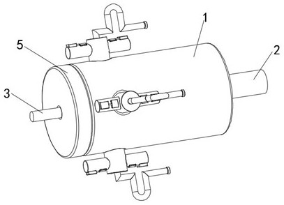
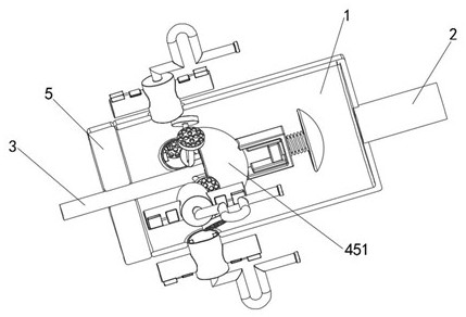
[0032] see Figure 1-7 , an energy-saving and environment-friendly furnace flue gas treatment device, comprising a cylinder body 1, an air inlet pipe 2 is fixedly connected to the right side of the cylinder body 1, an activated carbon filter layer 5 is fixedly connected to the left side of the cylinder body 1, The left side of the cylinder 1 is provided with a water inlet pipe 3, the water inlet pipe 3 penetrates the activated carbon filter layer 5 and extends into the inside of the cylinder 1, and the right side of the water inlet pipe 3 is fixed inside the cylinder 1 A spray device 4 is connected, a discharge device 6 is fixedly connected to the axially outer side of the cylinder 1, a dredging device 7 is arranged on the inside of the discharge device 6, and a protective device is fixedly installed on the outer wall of the discharge device 6 8;

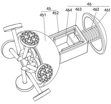
[0033] The spray device 4 includes a transition chamber 41, a solenoid valve 42, a spray pipe 43, a spray block 44, a dispersing ...


PUM


Abstract

The invention discloses an energy-saving and environment-friendly furnace flue gas treatment device which comprises a barrel; a gas inlet pipe is fixedly connected to the right side of the barrel; a spraying device comprises a transition chamber, an electromagnetic valve, a spraying pipe, a spraying block, a dispersion assembly and a detection device; the transition chamber is connected to the right side of the water inlet pipe; the electromagnetic valve is fixedly connected to the left side of the transition chamber; the spraying pipe is connected to the left side of the electromagnetic valve; the spraying block is fixedly connected to the end, away from the electromagnetic valve, of the spraying pipe; the dispersion assembly is fixedly installed on the right side of the transition chamber through a cylindrical rod; and the detection device is arranged on the dispersion assembly. According to the energy-saving and environment-friendly furnace flue gas treatment device, the purpose of reasonably adapting to water flow sprayed outwards according to the introduction amount of furnace flue gas is achieved through the matching effect of the stress rod, the shifting block, the slide rheostat and the electromagnetic valve, so that water resources are reasonably utilized, the water resources are further saved, and the purposes of energy conservation and environment protection are achieved.

Description

technical field [0001] The invention relates to the technical field of waste gas treatment, in particular to an energy-saving and environment-friendly furnace flue gas treatment device. Background technique [0002] Furnace flue gas will be generated during the production process of submerged arc furnaces, which contain a large amount of harmful substances, and it is necessary to effectively purify the flue gas from the furnace before it can be discharged. With the continuous development of science and technology, for the furnace Kiln flue gas treatment devices tend to be more and more energy-saving and environmentally friendly. [0003] The existing furnace flue gas treatment devices mainly have the following technical defects: First, spray purification is usually the main method of gas purification. The traditional spray spray device adopts the direct convection of gas and liquid. If it is too large, it will consume a lot of water resources, and at the same time, a large ...

Claims


Application Information

Patent Timeline
Patent Type & Authority Applications(China)
IPC IPC(8): B01D53/18
CPCB01D53/18
Inventor 武蔷薇
Owner 武蔷薇
Why Eureka
Try Eureka