Additive manufacturing method of integrated injector

An additive manufacturing and injector technology, which is applied in the field of metal additive manufacturing, can solve the problems of strict sealing effect requirements, high welding precision requirements, uncoordinated deformation, etc., and achieves reduction of processes, high reliability, and avoidance of uncoordinated deformation. Effect

Active Publication Date: 2022-02-11
合肥中科重明科技有限公司 +1
View PDF5 Cites 1 Cited by
  • Summary
  • Abstract
  • Description
  • Claims
  • Application Information

AI Technical Summary

Problems solved by technology

[0005] Aiming at the deficiencies of the prior art, the present invention provides an additive manufacturing method for an integrated injector, which solves the problem of butt welding in the manufacturing method in which the injector structure is generally composed of multiple parts through assembly, welding, etc. High precision requirements, strict requirements on sealing effect, and safety problems such as uncoordinated deformation and leakage are prone to occur

Method used


Image

  • Additive manufacturing method of integrated injector
  • Additive manufacturing method of integrated injector
  • Additive manufacturing method of integrated injector

Examples


Embodiment 1

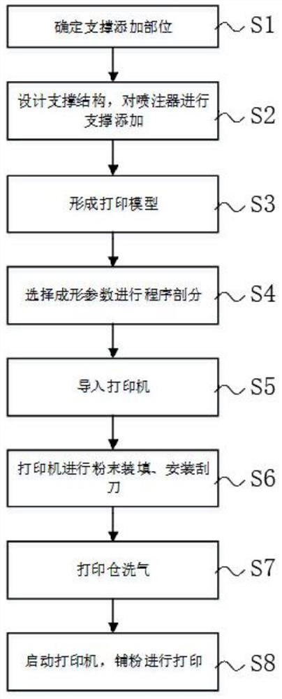
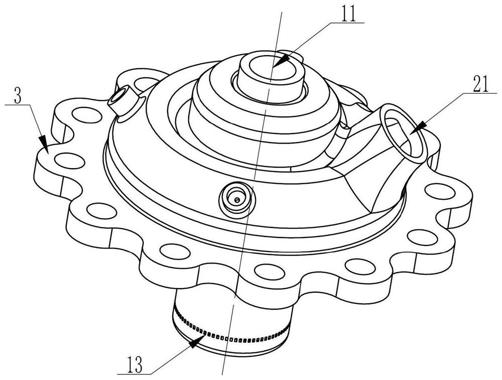
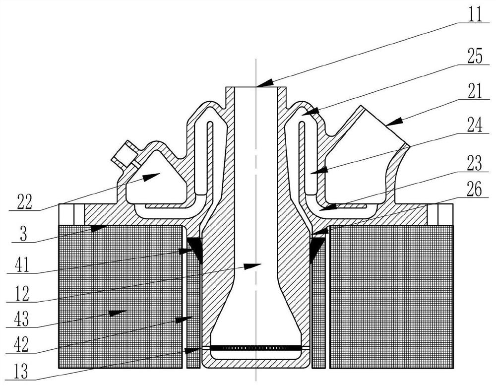
[0047] Figure 1-3 It is an embodiment of the present invention: an additive manufacturing method of an integrated injector, the additive manufacturing method is laser selective melting forming, and the forming method realization steps include:

[0048] S1. Determine the location where the support is added, make sure that the fuel inlet of the injector is placed upwards, and determine the lower end of the mounting flange and the location where the support is added;

[0049] S2. Design the support structure, add support to the injector, design solid support and block support structure, and add support to the integrated injector;

[0050] S3, forming a printing model, combining the three-dimensional model of the integrated injector and the designed support structure to form a printing model;

[0051] S4. Select the forming parameters for program subdivision, select the injector's solid support, block support, surface layer and solid forming parameters for program subdivision; ...

Embodiment 2

[0074] Figure 1-3 It is an embodiment of the present invention: an additive manufacturing method of an integrated injector, the additive manufacturing method is laser selective melting forming, and the forming method realization steps include:

[0075] S1. Determine the location where the support is added, make sure that the fuel inlet of the injector is placed upwards, and determine the lower end of the mounting flange and the location where the support is added;

[0076] S2. Design the support structure, add support to the injector, design solid support and block support structure, and add support to the integrated injector;

[0077] S3, forming a printing model, combining the three-dimensional model of the integrated injector and the designed support structure to form a printing model;

[0078] S4. Select the forming parameters for program subdivision, select the injector's solid support, block support, surface layer and solid forming parameters for program subdivision; ...

Embodiment 3

[0101] Figure 1-3 It is an embodiment of the present invention: an additive manufacturing method of an integrated injector, the additive manufacturing method is laser selective melting forming, and the forming method realization steps include:

[0102] S1. Determine the location where the support is added, make sure that the fuel inlet of the injector is placed upwards, and determine the lower end of the mounting flange and the location where the support is added;

[0103] S2. Design the support structure, add support to the injector, design solid support and block support structure, and add support to the integrated injector;

[0104] S3, forming a printing model, combining the three-dimensional model of the integrated injector and the designed support structure to form a printing model;

[0105] S4. Select the forming parameters for program subdivision, select the injector's solid support, block support, surface layer and solid forming parameters for program subdivision; ...


PUM

PropertyMeasurementUnit
particle diameteraaaaaaaaaa

Abstract

The invention relates to the technical field of metal additive manufacturing, in particular to an additive manufacturing method of an integrated injector. The additive manufacturing method is selective laser melting forming, and the forming method comprises the implementation steps of: determining a support adding part; designing a supporting structure; forming a printing model; selecting forming parameters for program subdivision, and selecting entity support, block support, surface layer and entity forming parameters of the injector for program subdivision; importing into a printer, namely importing a program package endowed with the forming parameters into the printer; filling the printer with powder raw materials, and installing a scraper; conducting gas washing on a printing bin, and introducing atmosphere into the printing bin for gas washing; and starting the printer, spreading powder by a scraper, and carrying out printing. According to the additive manufacturing method, the safety problems of high requirement on welding precision, strict requirement on sealing effect, easy occurrence of deformation and incoordination, leakage and the like in a manufacturing method for forming an assembly by a plurality of parts through assembling, welding and the like in an injector structure are solved.

Description

technical field [0001] The invention relates to the technical field of metal additive manufacturing, in particular to an additive manufacturing method for an integrated injector of a rocket engine. Background technique [0002] The injector of a rocket engine is an important component for injecting fuel and oxidant into the combustion chamber in a certain proportion for full atomization and mixing. The resistance loss is small, but also to ensure high structural strength, but also to ensure that high temperature does not fail. Therefore, injectors with complex internal cavity flow paths are constantly developing towards higher reliability, higher precision, and lower mass. [0003] In the traditional manufacturing process, the injector structure is generally assembled and welded by multiple parts to form an assembly. The disadvantages of this method are: when welding is used, the welding precision is high and the sealing effect is strict. It is also prone to safety issues ...

Claims


Application Information

Patent Timeline
Patent Type & Authority Applications(China)
IPC IPC(8): B22F10/28B22F10/31B22F5/10B22F10/40B22F12/67B22F10/85B33Y10/00B33Y30/00B33Y50/02B33Y80/00
CPCB22F10/28B22F10/31B22F5/10B22F10/40B22F12/67B22F10/85B33Y10/00B33Y30/00B33Y50/02B33Y80/00Y02P10/25
Inventor 鲁碧为赵林英范学军
Owner 合肥中科重明科技有限公司
Why Eureka
Try Eureka