
Electrical contact system for a switching device

A switchgear, electrical contact technology, applied in electrical switches, contacts, circuits, etc., can solve the problems of the rolling motion limitation of the contact piece, shorten the service life of the contact system, large mechanical load, etc., and achieve the effect of preventing contact welding

Pending Publication Date: 2022-02-11
JOHNSON ELECTRIC GUANGDONG CO LTD
View PDF17 Cites 0 Cited by
  • Summary
  • Abstract
  • Description
  • Claims
  • Application Information

AI Technical Summary

Problems solved by technology

However, this will result in a greater mechanical load than the direct connection of the spring element to the movable contact as described above
Besides that, it has the disadvantage that the springs get hot, which can lead to deformation of the slider, which shortens the life of the contact system
Furthermore, since the contact carrier is deformed during a short circuit due to the following conditions, the rolling-off movement of the contacts is restricted
Where the spring element is connected to the movable contact, for example by riveting, the high stiffness leads to a reduced flexibility of the spring element and thus limits the rolling-off movement of the contact

Method used


Image

  • Electrical contact system for a switching device
  • Electrical contact system for a switching device
  • Electrical contact system for a switching device

Examples


Embodiment Construction

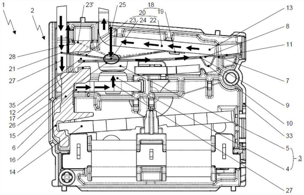
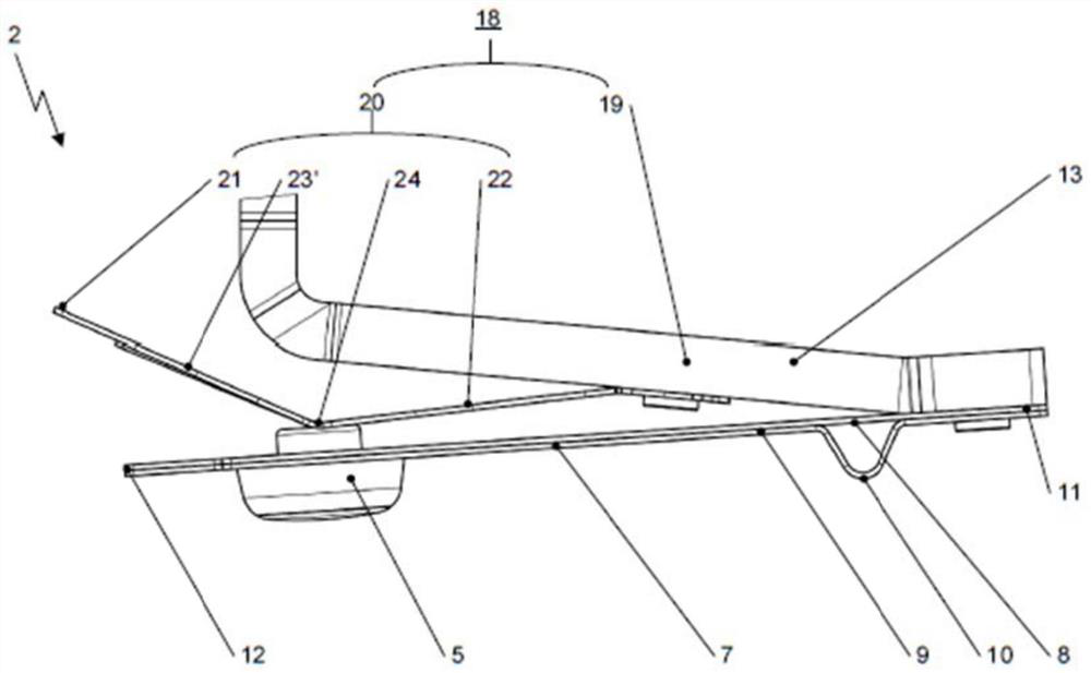
[0036] figure 1 A schematic sectional view of a relay 1 as an example of a switching device 1 is shown, in which an electrical contact system 2 having the features of the invention is applied. Said electrical contact system 2 comprises at least one pair of contacts 3 formed by a pair of contacts 4 , 5 . Here, at least one pair of contacts comprises a fixed contact 4 connected to a first bus bar 6 having a fixed position relative to the housing 33 of the switchgear, and a movable contact 5 which can be positioned relative to the The fixed contact piece 4 moves to perform the switching function, so that the contact pieces of the contacts are positioned relative to each other in such a way that the movable contact piece 5 can be pressed against the fixed contact piece 4 by contact force.

[0037] In addition, the electrical contact system 2 includes a planar contact carrier 7 for at least one movable contact 5 . The contact carrier 7 can have spring properties and is therefore ...


PUM


Abstract

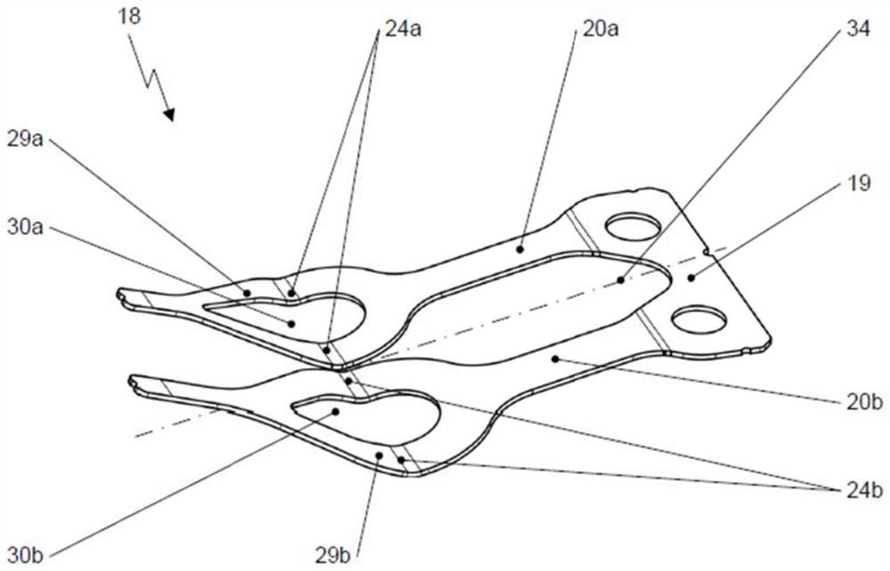
An electrical contact system (2) for a switching device (1). The system includes at least one pair of contacts (3) having a fixed contact piece (4) and a contact piece (5). The contact piece (5) is coupled to a slide (15). A planar contact piece carrier (7) extends in the longitudinal section thereof and is attached at the first end (11) to a second busbar (13). A second end (12) of the contact piece carrier (7) is coupled to the slide (5). A spring element (18) having a first spring arm section (22), a second spring arm section (23) and a pressure region (24) arranged therebetween in the area of the movable contact piece (5). The first spring arm section (22) is attached to the second busbar (13) at the first end (11). The second spring arm section (23) is also coupled at the free end (21) thereof to the slide (15).

Description

technical field [0001] The invention relates to an electrical contact system for a switchgear, wherein the switchgear used in the invention may include relays, switches, contactors and circuit breakers. Background technique [0002] Switching devices such as relays, switches, contactors and circuit breakers should have the following characteristics: high efficiency due to low resistance between connection terminals, low losses, and safety during operation of the equipment, especially during heating and A fire protection aspect as well as a long service life, which means as many switching operations as possible under load; and a protection against the contacts sticking to each other due to high short-circuit currents, for example in the event of an electrical fault. [0003] In conventional switching devices, a spring element ensures that the movable contact is lifted quickly away from the fixed contact when the contact is released, thereby reducing wear on the contact. [0...

Claims


Application Information

Patent Timeline
Patent Type & Authority Applications(China)
IPC IPC(8): H01H3/02H01H3/54
CPCH01H3/54H01H3/02H01H1/54H01H1/26H01H2001/265H01H50/54H01H50/56H01H50/642H01H51/2227
Inventor 马克思·赫尔曼艾瑞克·赫佐格尼尔斯·戈勒
Owner JOHNSON ELECTRIC GUANGDONG CO LTD
Learn More