
Delamination resistant glass containers with heat-tolerant coatings

a technology of glass containers and heat-tolerant coatings, applied in the field of glass containers, can solve the problems of increased likelihood of cracks in glass, mechanical damage on the surface of the package, and limited glass use in pharmaceutical packaging

Active Publication Date: 2014-01-02
CORNING INC
View PDF15 Cites 18 Cited by
  • Summary
  • Abstract
  • Description
  • Claims
  • Application Information

AI Technical Summary

Benefits of technology

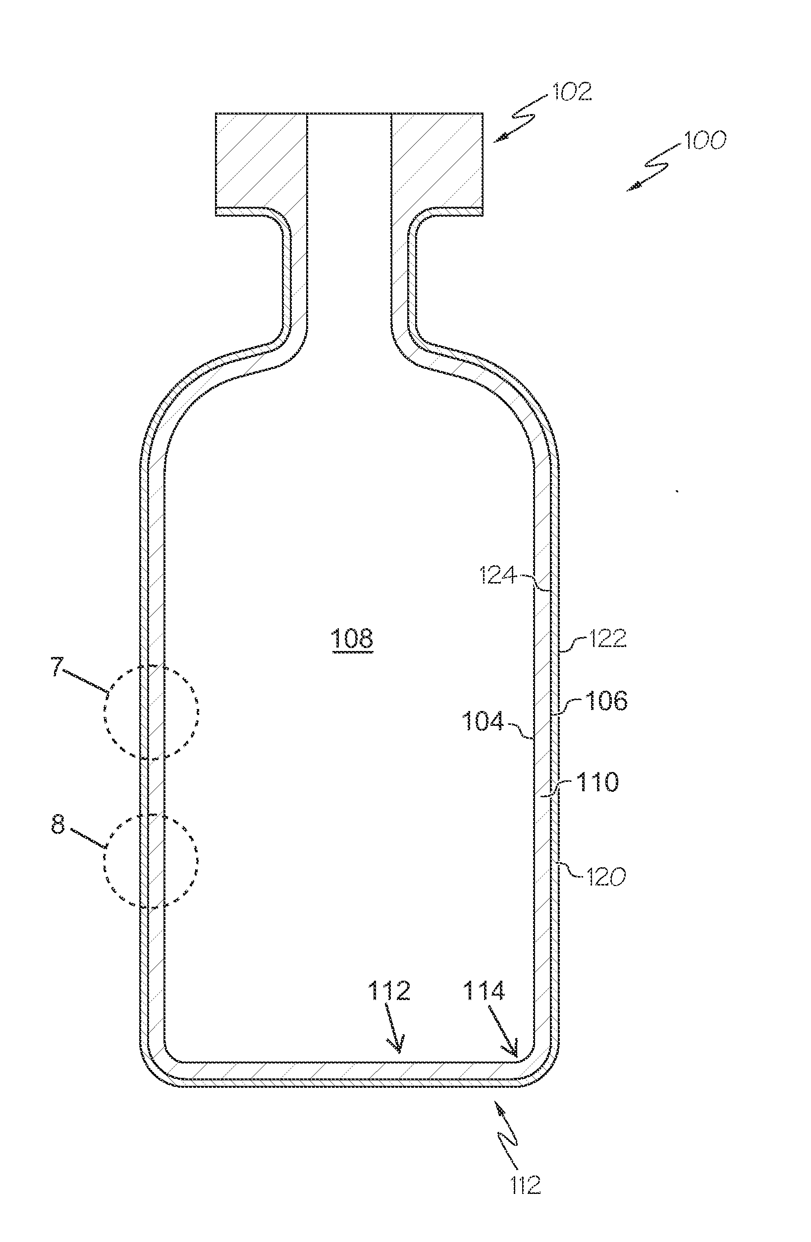
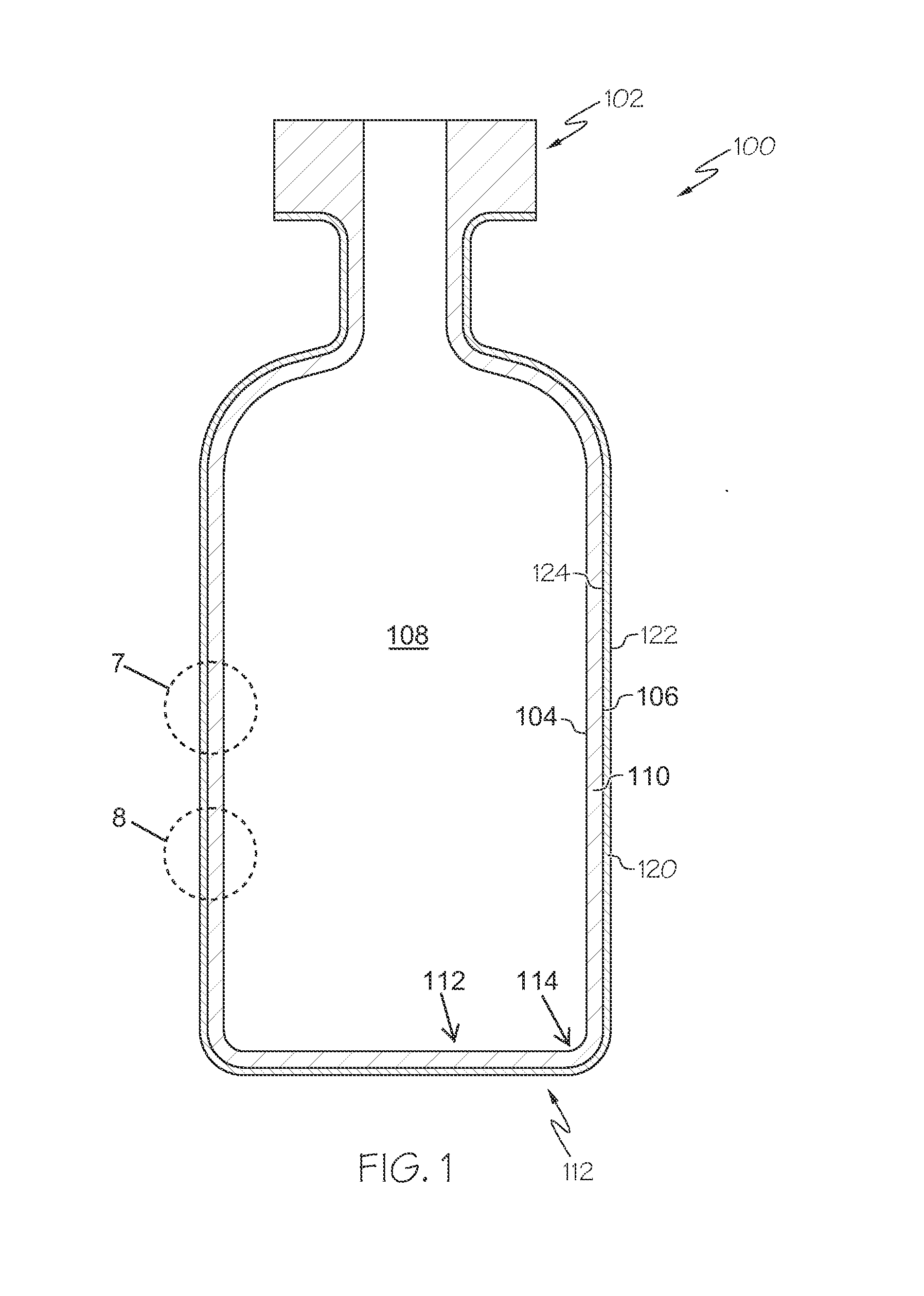
The patent describes a glass container with a heat-tolerant coating that can withstand high temperatures. The coating is bonded to the interior and / or exterior surface of the glass body and has a persistent layer of homogeneity. The glass body has a delamination factor of less than or equal to 3 and a threshold diffusivity of greater than or equal to 16 μm2 / hr at a temperature less than or equal to 450°C for at least 30 minutes. The heat-tolerant coating can be thermally stable at a temperature of at least 260°C for 30 minutes. The glass container can be formed from a specific glass composition and the heat-tolerant coating can include a coupling agent layer and a low-friction layer. The technical effect of the patent is to provide a glass container with improved heat resistance and durability.

Problems solved by technology

Although Type 1A and Type 1B glass compositions are commonly used in pharmaceutical packages, they do suffer from several deficiencies, including a tendency for the interior surfaces of the pharmaceutical package to shed glass particulates or “de-laminate” following exposure to pharmaceutical solutions.
In addition, use of glass in pharmaceutical packaging may also be limited by the mechanical performance of the glass.
Specifically, the high processing speeds utilized in the manufacture and filling of glass pharmaceutical packages may result in mechanical damage on the surface of the package, such as abrasions, as the packages come into contact with processing equipment, handling equipment, and / or other packages.
This mechanical damage significantly decreases the strength of the glass pharmaceutical package resulting in an increased likelihood that cracks will develop in the glass, potentially compromising the sterility of the pharmaceutical contained in the package.

Method used


Image

  • Delamination resistant glass containers with heat-tolerant coatings
  • Delamination resistant glass containers with heat-tolerant coatings
  • Delamination resistant glass containers with heat-tolerant coatings

Examples


example 1

[0231]Six exemplary inventive glass compositions (compositions A-F) were prepared. The specific compositions of each exemplary glass composition are reported below in Table 2. Multiple samples of each exemplary glass composition were produced. One set of samples of each composition was ion exchanged in a molten salt bath of 100% KNO3 at a temperature of 450° C. for at least 5 hours to induce a compressive layer in the surface of the sample. The compressive layer had a surface compressive stress of at least 500 MPa and a depth of layer of at least 45 μm.

[0232]The chemical durability of each exemplary glass composition was then determined utilizing the DIN 12116 standard, the ISO 695 standard, and the ISO 720 standard described above. Specifically, non-ion exchanged test samples of each exemplary glass composition were subjected to testing according to one of the DIN 12116 standard, the ISO 695 standard, or the ISO 720 standard to determine the acid resistance, the base resistance or ...

example 2

[0237]Three exemplary inventive glass compositions (compositions G-I) and three comparative glass compositions (compositions 1-3) were prepared. The ratio of alkali oxides to alumina (i.e., Y:X) was varied in each of the compositions in order to assess the effect of this ratio on various properties of the resultant glass melt and glass. The specific compositions of each of the exemplary inventive glass compositions and the comparative glass compositions are reported in Table 3. The strain point, anneal point, and softening point of melts formed from each of the glass compositions were determined and are reported in Table 3. In addition, the coefficient of thermal expansion (CTE), density, and stress optic coefficient (SOC) of the resultant glasses were also determined and are reported in Table 3. The hydrolytic resistance of glass samples formed from each exemplary inventive glass composition and each comparative glass composition was determined according to the ISO 720 Standard bot...

example 3

[0243]Three exemplary inventive glass compositions (compositions J-L) and three comparative glass compositions (compositions 4-6) were prepared. The concentration of MgO and CaO in the glass compositions was varied to produce both MgO-rich compositions (i.e., compositions J-L and 4) and CaO-rich compositions (i.e., compositions 5-6). The relative amounts of MgO and CaO were also varied such that the glass compositions had different values for the ratio (CaO / (CaO+MgO)). The specific compositions of each of the exemplary inventive glass compositions and the comparative glass compositions are reported below in Table 4. The properties of each composition were determined as described above with respect to Example 2.

TABLE 4Glass properties as function of CaO contentComposition Mole %JKL456SiO276.9977.1077.1077.0176.9777.12Al2O35.985.975.965.965.975.98Na2O11.3811.3311.3711.3811.4011.34K2O0.100.100.100.100.100.10MgO5.234.793.782.831.840.09CaO0.070.451.452.463.475.12SnO20.200.190.190.190.190...


PUM

PropertyMeasurementUnit
temperatureaaaaaaaaaa

Abstract

Delamination resistant glass containers with heat-tolerant coatings are disclosed. In one embodiment, a glass container may include a glass body having an interior surface, an exterior surface and a wall thickness extending from the exterior surface to the interior surface. At least the interior surface of the glass body is delamination resistant. The glass container may further include a heat-tolerant coating positioned on at least a portion of the exterior surface of the glass body. The heat-tolerant coating may be thermally stable at temperatures greater than or equal to 260° C. for 30 minutes.

Description

CROSS REFERENCE TO RELATED APPLICATIONS[0001]The present specification claims priority to U.S. Provisional Patent Application No. 61 / 665,682 filed Jun. 28, 2012 and entitled “Delamination Resistant Glass Containers with Heat Resistant Coatings;” U.S. Provisional Patent Application Ser. No. 61 / 656,998 filed Jun. 7, 2012 and entitled “Delamination Resistant Glass Containers;” U.S. patent application Ser. No. 13 / 660,394 filed Oct. 25, 2012 and entitled “Glass Compositions With Improved Chemical And Mechanical Durability;” and U.S. patent application Ser. No. 13 / 780,740 filed Feb. 28, 2013 and entitled “Glass Articles With Low Friction Coatings,” each of which is incorporated by reference herein.BACKGROUND[0002]1. Field[0003]The present specification generally relates to glass containers and, more specifically, to glass containers for use in storing perishable products including, without limitation, pharmaceutical formulations.[0004]2. Technical Background[0005]Historically, glass has b...

Claims


Application Information

Patent Timeline
Patent Type & Authority Applications(United States)
IPC IPC(8): B65D1/40
CPCB65D1/40C03C17/42C03C21/002C09D179/08C03C2217/78C08G73/105C08G73/1071C03C3/087C03C17/3405C08K5/544C03C17/005C08L83/04C08L79/08B65D23/0814C03C17/30C03C17/32B65D25/34C03C2218/111B32B17/06B65D1/42B65D13/02C03C17/28A61J1/1468B65D25/14Y10T428/131C03B23/047
Inventor FADEEV, ANDREI GENNADYEVICHCHANG, THERESABOOKBINDER, DANA CRAIGPAL, SANTONASAHA, CHANDAN KUMARDEMARTINO, STEVEN EDWARDTIMMONS, CHRISTOPHER LEEPEANASKY, JOHN STEPHENSCHAUT, ROBERT ANTHONYDANIELSON, PAUL STEVENDRAKE, MELINDA ANNMORENA, ROBERT MICHAELADIB, KAVEH
Owner CORNING INC
Learn More