Differential current-to-voltage conversion

A technology of differential current and voltage conversion circuit, applied in the direction of differential amplifiers, electrical components, charge amplifiers, etc., to achieve the effect of improving the power supply rejection ratio

Pending Publication Date: 2022-02-11
AMS INT
View PDF0 Cites 0 Cited by
  • Summary
  • Abstract
  • Description
  • Claims
  • Application Information

AI Technical Summary

Problems solved by technology

The large ratio between the magnitude of the DC current signal and the magnitude of the AC current signal makes it challenging to detect small AC current signals in the presence of strong ambient light or DC current signals

Method used


Image

  • Differential current-to-voltage conversion
  • Differential current-to-voltage conversion
  • Differential current-to-voltage conversion

Examples


Embodiment Construction

[0015] In the following paragraphs, the differential current-to-voltage conversion circuit 10 is described in the context of a proximity sensor comprising a light emitter (eg, a VCSEL or LED) and a light detector (eg, a photodiode). However, the differential current-to-voltage conversion circuit 10 may be used in other applications, including applications where it is desired to sense relatively small current signals.

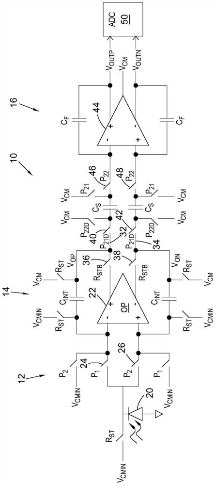
[0016] Such as figure 1 As shown, differential current-to-voltage conversion circuit 10 includes an input sampling stage 12 , a differential integration and DC signal cancellation stage 14 , and an amplification and accumulator stage 16 . Circuit 10 may be fabricated, for example, as an integrated semiconductor circuit using standard digital CMOS design and fabrication techniques.

[0017] The input sampling stage 12 is configured to receive a current signal from a current generating device, which in the example shown is a photodetector (eg a photodiode) 20 of ...


PUM


Abstract

An apparatus includes a differential current-to-voltage conversion circuit that includes an input sampling stage circuit, a differential integration and DC signal cancellation stage circuit, and an amplification and accumulator stage circuit. An input common mode voltage of the differential current-to-voltage circuit is independent of an output common mode voltage of the differential current-to-voltage circuit.

Description

technical field [0001] The present disclosure relates to differential current to voltage conversion. Background technique [0002] Various applications in electronic circuits require the measurement of relatively small current signals. For example, in the context of optical proximity sensing, detecting a pulsed AC light signal emitted from a light emitter and reflected from an object to be detected produces a small AC current signal in the presence of a large ambient light DC current signal. When the photoemitter is turned on, the ambient light-induced DC current generated by the photodetector is typically many times greater than the reflected light-induced AC current generated by the photodetector. The large ratio between the magnitude of the DC current signal and the magnitude of the AC current signal makes it challenging to detect small AC current signals in the presence of strong ambient light or DC current signals. Contents of the invention [0003] The differential...

Claims


Application Information

Patent Timeline
Patent Type & Authority Applications(China)
IPC IPC(8): H03F1/08H03F3/00H03F3/08H03F3/45H03F3/70
CPCH03F1/086H03F3/082H03F3/45475H03F3/087H03F3/70H03F3/005H03F2203/45562H03F2203/45141H03F2203/45174H03F2200/252H03F2200/264H03F2203/45134H03F2203/45614H03F2200/312H03F2200/411H03F2200/81H03F2203/45206H03F2203/45512H03F2203/45616H03F2203/45634H03F2203/45726H03F2203/45171H03F2200/421H03F2203/45138H03F2203/45514H03F2203/45551H03H19/004H03K3/012H03K3/013
Inventor R.托塔蒂尔R.K.阿杜苏马利帕瓦蒂.S.杰V.B.武利加达拉
Owner AMS INT
Why Eureka
Try Eureka