Hydraulic integrated oil cylinder barrel and machining method thereof

A technology of hydraulic integration and processing method, which is applied in the direction of fluid pressure actuating device, using stable tension/pressure testing material strength, measuring device, etc. To meet the requirements, cylindricity influence, performance degradation and other issues, to achieve the effect of simple alignment and positioning and clamping, ensuring the requirements of various geometric tolerances, and solving the bottleneck of the processing technology

Active Publication Date: 2022-02-15
HUBEI JIANGSHAN HEAVY IND
View PDF5 Cites 4 Cited by
  • Summary
  • Abstract
  • Description
  • Claims
  • Application Information

AI Technical Summary

Problems solved by technology

However, the integrated cylinder barrel has many welding parts, large welding deformation, and poor structural craftsmanship; and at present, there is no effective and efficient processing method for this kind of integrated oil cylinder cylinder structure.
The welded parts such as the oil port and oil seat welded on the outer circle of the integrated oil cylinder are easy to affect the cylindricity of the inner hole of the cylinder during welding, which will increase the leakage in the integrated oil cylinder and reduce the performance
The cylinder bottom valve seat of the integrated oil cylinder must be welded to one end of the cylinder and connected to the valve group; when the cylinder bottom valve seat is welded to the cylinder, due to welding deformation, the cylinder bottom valve seat is connected to the control valve group The flatness of the plane does not meet the requirements, and the gap of the connecting surface under the high-pressure oil often causes the sealing ring to be damaged, and the oil sealing performance of the sealing ring decreases, and it is very easy for the hydraulic oil to run, pop, drip, and leak.

Method used


Image

  • Hydraulic integrated oil cylinder barrel and machining method thereof

Examples


Embodiment Construction

[0025] The present invention will be further described below according to the embodiments provided by the accompanying drawings.

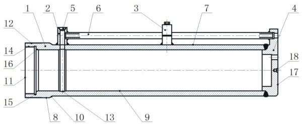
[0026] Step 1, when the workpiece is blanked and roughed, after the cylinder 1 blank is blanked, the cylinder 1 blank is subjected to rough turning of the outer circle and both ends of the cylinder; the cylinder 1 blank is made of steel pipe, and Leave a machining allowance, the machining allowance of each outer circle of the cylinder 1 blank is not less than 5mm, the machining allowance of the inner hole 9 is not less than 5mm, and the total length of the cylinder 1 blank is not less than 15mm; on the lathe, the inner hole 9 Clamp the blank of the cylinder 1 for the positioning reference, and clamp it with two tops, use the three-jaw chuck and the top of the tailstock of the lathe to respectively press the two ends of the inner hole 9, and the rough turning of the cylinder 1 blank reaches the outer circle. See the light; take the outer circle of t...


PUM

PropertyMeasurementUnit
surface smoothnessaaaaaaaaaa

Abstract

The invention provides a hydraulic integrated oil cylinder barrel and a machining method thereof. The machining method comprises the steps of workpiece blanking and rough turning machining, primary welding and flaw detection after welding, boring and grinding combination and fractional finish turning, secondary welding and flaw detection after welding, center hole punching and end face turning and grinding, third welding and flaw detection after welding, pressure resistance testing and follow-up treatment. On the premise that special tools, tools and equipment are not needed, an existing numerical control lathe, an existing deep hole boring machine, an existing deep hole honing machine tool and an existing universal cylindrical grinding machine are directly utilized, the technological process is reasonably arranged, technological parameters are determined, the machining precision of workpieces is reliably guaranteed, machining deformation is greatly prevented, and the flatness of the connecting plane of the cylinder bottom valve seat and the control valve set is guaranteed.

Description

technical field [0001] The invention belongs to the field of mechanical processing and hydraulic transmission, and in particular relates to a processing method of a hydraulic integrated oil cylinder barrel. Background technique [0002] The cylinder barrel of the hydraulic integrated oil cylinder is welded to the cylinder barrel through multiple welding parts such as the oil port, oil pipe, and cylinder bottom valve seat, so as to realize the integration of the inlet and outlet ports on the cylinder bottom valve seat of the cylinder barrel. Install the hydraulic control valve group directly on the cylinder barrel of the cylinder bottom valve seat. This kind of integrated oil cylinder simplifies the installation of the oil circuit of the hydraulic system, effectively reduces the installation and use space of the oil cylinder control pipeline, and avoids the disorder and confusion of the installation of the hydraulic cylinder control oil circuit and oil pipe. This kind of hydr...

Claims


Application Information

Patent Timeline
Patent Type & Authority Applications(China)
IPC IPC(8): F15B15/20F15B15/14B23P15/00G01N3/12
CPCF15B15/1428B23P15/00G01N3/12G01N2203/0003G01N2203/0019G01N2203/0048
Inventor 付士云黄良卓韩新庆左飞胡云才付朝霞洪伟锋丁志平张贵永武雨航
Owner HUBEI JIANGSHAN HEAVY IND
Why Eureka
Try Eureka