
Hoisting, positioning and lubricating structure of reciprocating pump high-precision rack hole machining boring rod

A lubricating structure and high-precision technology, applied in boring bars, metal processing equipment, metal processing mechanical parts, etc., can solve the problems of unguaranteed processing accuracy, low efficiency and high cost

Pending Publication Date: 2022-02-18
黄秀芳
View PDF0 Cites 0 Cited by
  • Summary
  • Abstract
  • Description
  • Claims
  • Application Information

AI Technical Summary

Problems solved by technology

Now high-precision reciprocating pump design and manufacturing companies have made promises to users, and put forward the quality goal of free 10-year repair (the current reciprocating pump is free of charge for 1 year repair). Such target guarantee measures first require the accuracy of the reciprocating pump frame High, but due to the large size of the frame, the distance between various holes is very large, which can only be satisfied by boring processing method, and because the size tolerance of each hole of the frame is 6, and the shape and position tolerance between the axes is 4 to 6 Between the stages, because of the large size of the frame, the large hole distance inside the frame, and the shape and position tolerances of the axis to the axis, it is impossible to guarantee the machining accuracy by using expensive large-scale numerical control equipment at ordinary ambient temperatures. The cost is very high. In order to fully meet the high-precision requirements of the reciprocating pump frame, the processing method of special equipment structure and boring bar is adopted. In this method, there are the following three types of processing frame parts in common special equipment equipped with boring bar. Question: ① Due to the use of the boring bar, the machine frame has a compact structure, and the distance between the holes to be processed is large, and the five cylinders are the most. After the boring bar has processed one row of holes, it needs to move to another row of holes. There is a problem of how to move the boring bar to another row For some people, the method of moving is not good, and the efficiency is very low, which makes the auxiliary time of the processing frame too long; ②The movement of the boring bar will affect the reliability of the positioning accuracy of the boring bar. Position the copper sleeve, move the boring bar to another column, and use the boring bar to pass through the inner hole of the copper sleeve. In order to improve the positioning accuracy, the gap between the copper sleeve and the boring bar should be very small, but the problem caused by the small gap makes the long and heavy It is very difficult for the boring bar to pass through the copper sleeve with a very small gap and a fixed position, so some people sacrifice the positioning accuracy and design the gap between the boring bar and the copper sleeve to be very large; ③The lubrication of the commonly used copper sleeve and the boring bar is Design an oil cup, which is lubricated by a small amount of lubricating oil in the oil cup. Because the pressure and flow of the lubricating oil are too small, the copper sleeve wears quickly. When the copper sleeve is worn out, some people design it to shrink the copper sleeve to a small inner hole. , although the copper sleeve can shrink, the surface roughness of the copper sleeve is seriously reduced after the wear, which accelerates the wear of the boring bar and the copper sleeve

Method used


Image

  • Hoisting, positioning and lubricating structure of reciprocating pump high-precision rack hole machining boring rod
  • Hoisting, positioning and lubricating structure of reciprocating pump high-precision rack hole machining boring rod
  • Hoisting, positioning and lubricating structure of reciprocating pump high-precision rack hole machining boring rod

Examples


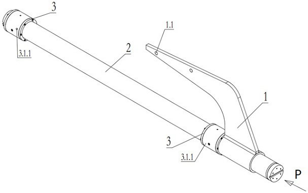
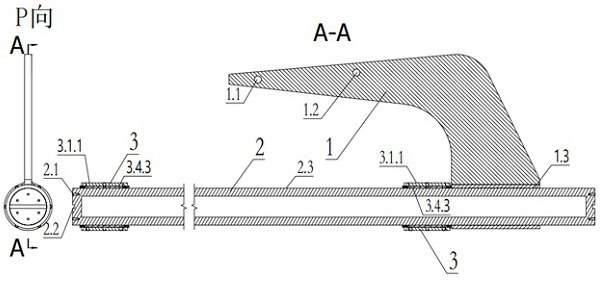
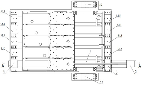
Embodiment Construction

[0025] The present invention will be further described below in conjunction with the accompanying drawings and specific embodiments.

[0026] The embodiments of the present invention are not limited to the following examples, and various changes made without departing from the gist of the present invention fall within the protection scope of the present invention.

[0027] The present invention is implemented taking the five-cylinder reciprocating pump above 2200hp as an example.

[0028] see Figure 1 to Figure 11 , the present embodiment is a hoisting, positioning and lubricating structure of a high-precision frame hole processing boring bar for a reciprocating pump, including a lifting tool 1, a boring bar 2, a copper sleeve part 3, a frame 4, a frame hole processing fixture 5, and an end Cavity 6 between cover and copper sleeve, hoisting hole 1.1, hoisting hole 1.2, installation hole 1.3, coupling screw hole 2.1, coupling groove 2.2, outer circle 2.3, copper sleeve seat 3.1...


PUM


Abstract

The invention discloses a hoisting, positioning and lubricating structure of a reciprocating pump high-precision rack hole machining boring rod, and relates to the field of petroleum engineering equipment. The hoisting, positioning and lubricating structure specifically comprises a lifting appliance, a boring rod, a copper sleeve part, a rack, a rack hole machining clamp, a cavity between an end cover and a copper sleeve, a lifting hole, an outer circle, a positioning outer circle, an oil inlet channel, an oil return channel, a friction inner hole, various copper sleeve part positioning and mounting holes and a copper sleeve part positioning and mounting hole gland. By adopting the hoisting, positioning and lubricating structure of the reciprocating pump high-precision rack hole machining boring rod, when the high-precision rack hole is machined, the boring rod and a copper bush part on the boring rod can be horizontally hoisted, so that the hoisting time for replacing the position of a machining hole is shortened easily through a compact hole space of a rack structure; the copper sleeve part is convenient to position and high in positioning precision, and the accurate position of the boring rod is guaranteed; and the outer circle of the boring rod and the friction inner hole of the copper sleeve part as a friction pair are fully lubricated, so that the service life of the friction pair can be prolonged.

Description

technical field [0001] The invention relates to the field of petroleum engineering equipment, in particular to a hoisting, positioning and lubricating structure of a boring bar for machining a high-precision frame hole of a reciprocating pump. Background technique [0002] Now there are two reciprocating pumps with very similar structures in the field of petroleum engineering equipment, namely drilling pumps and fracturing pumps. These two reciprocating pumps have a large frame, which is large in size and heavy in weight. For example, the frame of a drilling pump is 2700mm-2800mm long, 2000-2200mm wide, 1790mm-2000mm high, and 6500kg-8000kg in weight. The main motor driving the reciprocating pump, the crankshaft components, connecting rod components, crosshead components, valve box components, lubrication system components, spray system components, and almost all key components of the reciprocating pump should be installed on the frame of these two reciprocating pumps. The ...

Claims


Application Information

Patent Timeline
IPC IPC(8): B23B29/02B23B41/00B23Q11/12B66C1/10
CPCB23B29/02B23B41/00B23Q11/121B66C1/10
Inventor 黄秀芳
Owner 黄秀芳
Learn More