
Hub ventilation and heat dissipation device

A ventilation and heat dissipation, hub technology, which is applied to wind turbines, wind power generation, wind turbines, etc. in the same direction as the wind, and can solve problems such as operational accidents, corrosion of hub connection structures, and large power dependence

Pending Publication Date: 2021-07-30
中广核新能源蚌埠有限公司
View PDF1 Cites 0 Cited by
  • Summary
  • Abstract
  • Description
  • Claims
  • Application Information

AI Technical Summary

Problems solved by technology

[0003] However, there are still obvious defects in the above-mentioned heat dissipation system, heat dissipation method of the wind turbine and the wind turbine in use: 1. The above-mentioned device did not take into account the water inflow problem of the centrifugal fan in the design process, because the fan is exposed to the atmosphere. Among them, the internal structure of the hub needs proper waterproof protection. When external rainwater enters the interior of the hub, it will cause corrosion of the hub and its connecting structure, thereby affecting the life of the fan. At the same time, rainwater entering the interior of the fan blade connected to the hub will cause The center of gravity of the fan rotation is unstable, which in turn causes more serious operation accidents; 2. The above-mentioned device drives the centrifugal fan to work through electric power, resulting in a relatively single driving device for the fan and a greater dependence on power

Method used


Image

  • Hub ventilation and heat dissipation device
  • Hub ventilation and heat dissipation device
  • Hub ventilation and heat dissipation device

Examples


Embodiment

[0027] see Figure 1-6 , the present invention provides a technical solution:

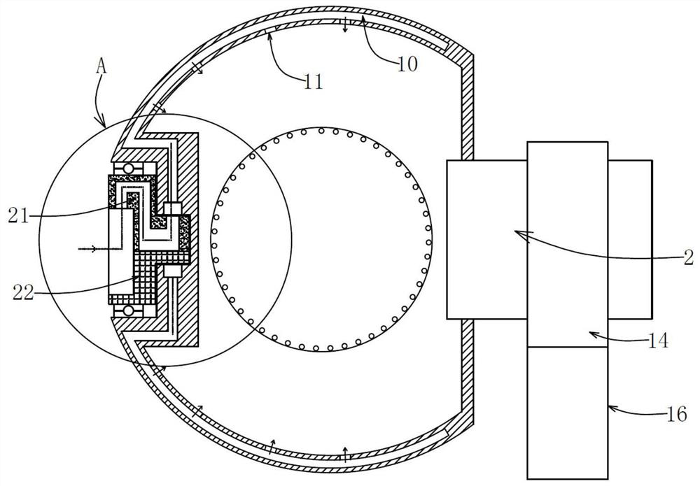
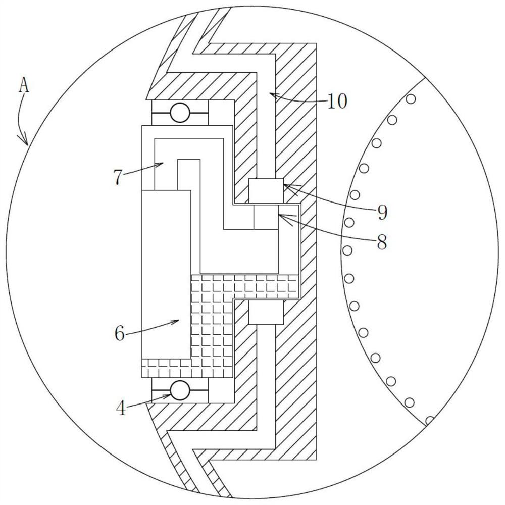
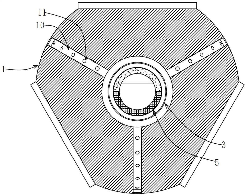
[0028] A wheel hub ventilation and heat dissipation device, comprising a wheel hub 1, a wind wheel shaft 2 is fixedly installed on the back side of the wheel hub 1, an air inlet groove 3 is opened on the windward side of the wheel hub 1, and a gravity offset ring is movably installed in the air inlet groove 3 through an offset bearing 4 5. There is a windward slot 6 in the gravity offset ring 5, and an S-shaped air inlet channel 7 is opened on the upper part of the windward slot 6, which runs through the rotation axis. The side of the gravity offset ring 5 has an S-shaped air inlet The air intake hole 8 through which the road 7 runs;

[0029] The mass distribution of the gravity deflection ring 5 of the present invention is uniform due to the substance filled inside. When the hub 1 rotates during the power generation process, the gravity deflection ring 5 maintains a fixed angle under the action o...


PUM


Abstract

The invention provides a hub ventilation and heat dissipation device. The hub ventilation and heat dissipation device comprises a hub, wherein a wind wheel shaft is fixedly installed at the back side of the hub; an air inlet groove is formed in the windward side of the hub; a gravity offset ring is movably installed in the air inlet groove through an offset bearing; an air inlet hole passing through an S-shaped air inlet channel is formed in the side edge of the rotating axis of the gravity offset ring; an annular air inlet groove is formed in the hub; the air inlet hole communicates with the annular air inlet groove; the annular air inlet groove communicates with a plurality of induced draft ducts arranged in a hub interlayer; an annular air outlet groove matched with the air outlet hole is formed in an air outlet ring; and an air return pipe is fixedly installed at the bottom of the air outlet ring. Through the arrangement of the gravity offset ring and the interlayer ducts in the hub, atmospheric precipitation is effectively prevented from entering the hub, and the interior of the hub is actively cooled through wind energy, so that the energy consumption of equipment is reduced, normal work of connecting parts in the hub is guaranteed, and the heat dissipation effect is improved.

Description

technical field [0001] The invention relates to the technical field of fan cooling devices, in particular to a hub ventilation and cooling device. Background technique [0002] In the prior art, the application number is "CN201611141780.7", a cooling system for a wind turbine, a cooling method and a wind turbine. The cooling system includes: a fan, one or more air inlets arranged on the outer wall of the shroud It is installed at the air outlet at the tail of the nacelle cover; the fan is installed at the air inlet, and the air inlet is in front of the hub. The heat dissipation method uses the heat dissipation system, and the wind turbine includes a heat dissipation system. The fan of this technology draws the air outside the wind turbine into the air inlet part, forms a positive pressure airflow in the air inlet part, flows into the windshield, and diverts the air through the windshield and the wheel hub, and respectively separates the upper winding of the engine stator and...

Claims


Application Information

Patent Timeline
IPC IPC(8): F03D1/06F03D80/60F03D15/00F16C3/02
CPCF03D1/0691F16C3/02F03D15/00F03D80/60Y02E10/72
Inventor 徐战昌韩明珠王其元黄骁田骏楠赵斌丁广恒周智涛杨建华
Owner 中广核新能源蚌埠有限公司
Learn More