Automatic welding device and process for reinforcing mesh

An automatic welding and steel mesh technology, applied in welding equipment, welding/welding/cutting items, manufacturing tools, etc., can solve the problem of unstable feeding of steel mesh longitudinal beams, desoldering or weak welding, and unsatisfactory quality of steel mesh and other issues to achieve the effect of improving welding quality, ensuring connection stability, and improving production capacity

Active Publication Date: 2022-02-18
GUIZHOU PANJIANG REFINED COAL
View PDF5 Cites 0 Cited by
  • Summary
  • Abstract
  • Description
  • Claims
  • Application Information

AI Technical Summary

Problems solved by technology

The biggest disadvantage of this process is that the production efficiency is low, it takes a lot of manpower and material resources, and the most important thing is that the quality of the welded steel mesh is not ideal.
[0003]The existing automatic wire mesh welding machine can realize automatic wire mesh welding, but on the one hand, the purchase cost of the whole system is high, on the other hand, the feeding of the steel mesh stringer is unstable, and often Offset leads to desoldering or weak welding, resulting in poor use effect

Method used


Image

  • Automatic welding device and process for reinforcing mesh
  • Automatic welding device and process for reinforcing mesh
  • Automatic welding device and process for reinforcing mesh

Examples


Embodiment 1

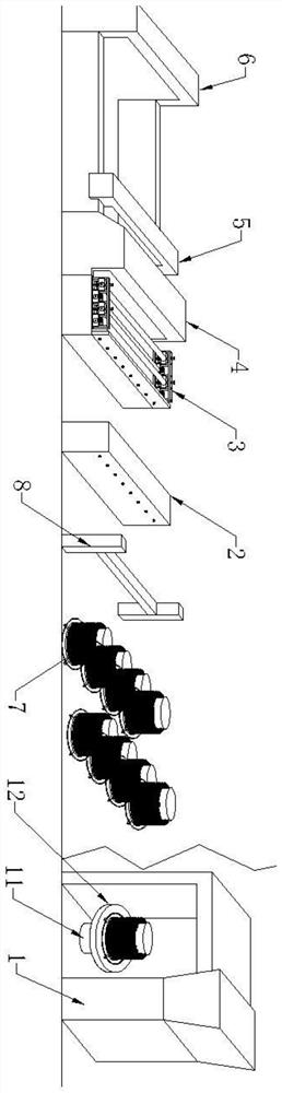
[0033] Such as Figure 1-5 As shown, a steel wire automatic welding device includes a wire drawing mechanism 1, a straightening mechanism 2, a feed mechanism 3, a welding mechanism 4, a mobile mechanism 5, and a cutting network mechanism 6.

[0034] The brushed mechanism 1 is a metal brigadier, which is provided at the front end of the straightening mechanism 2, which is used to draw the steel bar, which can improve the material utilization, and remove the surface oxide layer of the disc, which is advantageous for electric welding, improve the welding effect.

[0035] A plaque 7 is provided between the brushed mechanism 1 and the straightening mechanism 2, the arrangement frame 7 including a cylinder 71, a base 72, and a bracket 73, and the cylindrical 71 extends an excess of a disk 711. Above the disc 711, the four steel plates are welded to the cylinder to form a base 72, and the outer end of the base 72 is sequentially connected to the ring forming bracket 73. The reinforced mes...

Embodiment 2

[0044] An automatic welding process of steel wire, including the following steps:

[0045] S1: Using the brushed mechanism 1 to pull the diameter of 6 mm to 5.5 mm, and the disc is placed on the discharge rack 7, and the discharge frame 7 is placed on the turntable 12, and the turntable 12 is rotated. 7 load the steel bar strip;

[0046] S2: A portion of the steel bars after the wire is turned straight by the straightening mechanism 2 and cut off at a certain size, as the beam;

[0047] S3: Several of the plurality of places 7 in order, using straightening mechanism 2 straightened steel bars and toward the feed mechanism, as a stringer;

[0048] S4: Place the beam in the welded mechanism 4 feed slot, so that the beam automatic feed is formed with a grid, and the welding is completed;

[0049] S5: Using the mobile mechanism 5 to move the welded steel wire backward, and cut the stringer by cutting the network mechanism 6 to obtain a steel network of the design length.

[0050] Econo...


PUM


Abstract

The invention discloses an automatic welding device and process for a reinforcing mesh, and the automatic welding device is sequentially provided with a wire drawing mechanism, a pay-off rack, a straightening mechanism, a feeding mechanism, a welding mechanism, a moving mechanism and a mesh cutting mechanism in the moving direction of longitudinal bars. The production process comprises the steps of wire drawing, straightening (cutting), feeding, welding and automatic cutting to form the reinforcing mesh. The production efficiency and the production quality are greatly improved, the feeding mechanism is arranged at the front end of the welding mechanism, reinforcing steel bars are clamped through the upper feeding roller and the lower feeding roller, and the reinforcing steel bars stably enter the welding mechanism at a preset interval, so that deviation caused by jumping of the reinforcing steel bars is avoided, and the phenomenon of missing welding of the reinforcing steel bars is avoided.

Description

Technical field [0001] The present invention belongs to the field of welding technology, and in particular, there is a automatic welding device and process of steel wire mesh. Background technique [0002] Reinforced mesh is commonly used in mining engineering, producing equipment, and often welding steel networks from the reinforcement. At present, to complete the welding of steel wire, first use the straightening machine to pull the strip straight, cut into two different lengths of steel bars, and use the artificially stitching into a steel network, and then use the welding network to weld into the steel network. The biggest drawback of this process is that the production efficiency is low, it costs a lot of manpower, material, and the most important thing is that the quality of the welded steel network is not ideal. [0003] The existing automatic welding network machine can achieve automatic welding network, but on the one hand, the total purchase cost is high. On the other h...

Claims


Application Information

Patent Timeline
IPC IPC(8): B23K28/02B23K101/22
CPCB23K28/02B23K2101/22
Inventor 张新利叶文凯杨乘龙张波胡钟鸿熊天福
Owner GUIZHOU PANJIANG REFINED COAL
Why Eureka
Try Eureka