Deburring device for desk and chair machining

A technology for desks, chairs and burrs, which is applied in metal processing equipment, grinding/polishing safety devices, manufacturing tools, etc. easy sanding effect

Pending Publication Date: 2022-02-18
JIANGSU ZICHEN EDUCATION EQUIP
View PDF0 Cites 3 Cited by
  • Summary
  • Abstract
  • Description
  • Claims
  • Application Information

AI Technical Summary

Problems solved by technology

[0003] The desks and chairs include wooden ones. When the wooden materials are processed, burrs will be generated, and the burrs need to be removed. Since the edges of the desks and chairs are perpendicular to each other and the thickness of the table top is low, the common deburring devices on the ma

Method used


Image

  • Deburring device for desk and chair machining
  • Deburring device for desk and chair machining
  • Deburring device for desk and chair machining

Examples


Embodiment 1

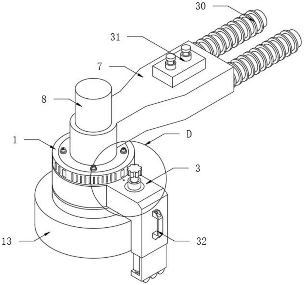
[0031] see Figure 1-6 , the present invention provides a technical solution: a deburring device for processing desks and chairs, the deburring device for processing desks and chairs includes

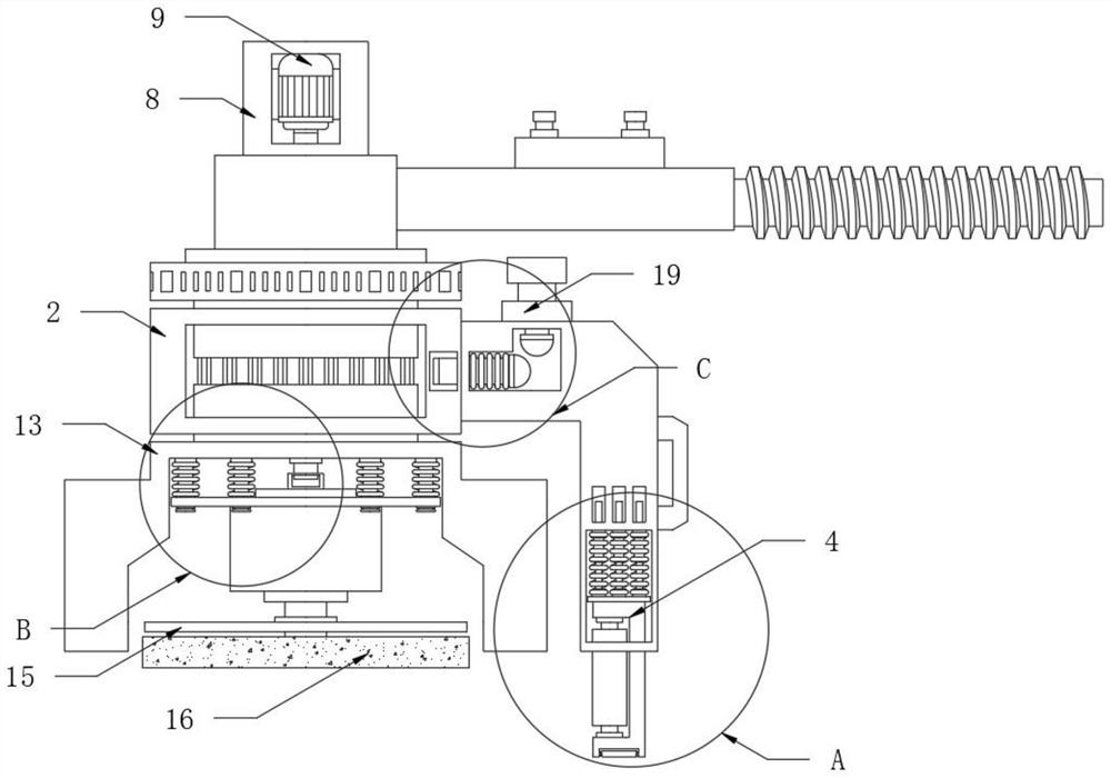
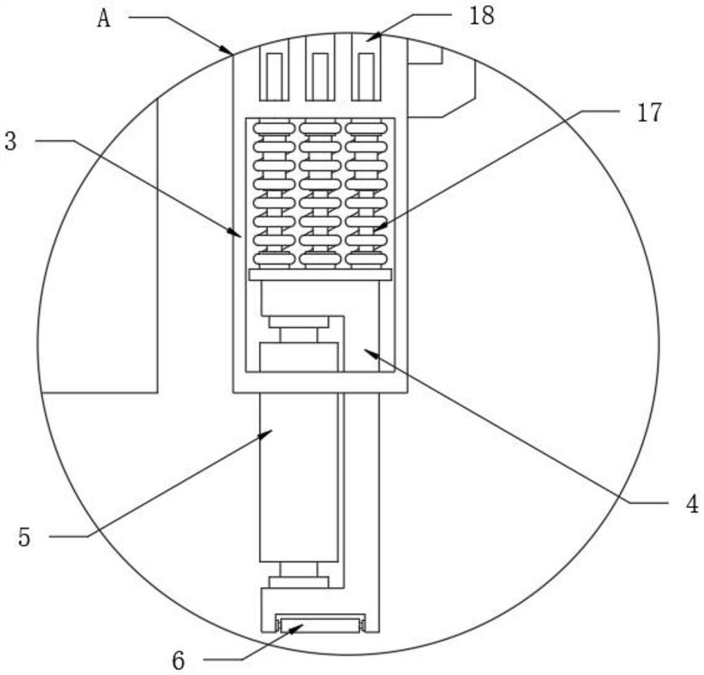
[0032] Fixed cylinder 1, the middle part of the fixed cylinder 1 is equipped with a fixed ring 2, the side of the fixed ring 2 away from the fixed cylinder 1 is fixedly installed with a connector 3, the bottom end of the connector 3 is provided with a bracket 4, and the bracket 4 is close to the fixed ring 2 A number of guide rollers 5 are arranged inside one side of the bracket 4, and a number of idler rollers 6 are arranged inside the bottom of the bracket 4;

[0033] Support plate 7, support plate 7 is connected to the top of fixed cylinder 1, and the top of support plate 7 is fixedly installed machine cover 8, and the inside of machine cover 8 is fixedly installed with first motor 9, and the output shaft end of first motor 9 is fixedly installed with A screw rod 10, the bottom end ...

Embodiment 2

[0045] A deburring device for processing desks and chairs, the deburring device for processing desks and chairs includes

[0046] Fixed cylinder 1, the middle part of the fixed cylinder 1 is equipped with a fixed ring 2, the side of the fixed ring 2 away from the fixed cylinder 1 is fixedly installed with a connector 3, the bottom end of the connector 3 is provided with a bracket 4, and the bracket 4 is close to the fixed ring 2 One side of the inside is provided with several guide rollers 5;

[0047] Support plate 7, support plate 7 is connected to the top of fixed cylinder 1, and the top of support plate 7 is fixedly installed machine cover 8, and the inside of machine cover 8 is fixedly installed with first motor 9, and the output shaft end of first motor 9 is fixedly installed with A screw rod 10, the bottom end of the screw rod 10 is movably connected with a sleeve 11, and the bottom of the sleeve 11 is fixedly connected with a mounting plate 12;

[0048] A protective co...


PUM


Abstract

The invention discloses a deburring device for desk and chair machining, and the device comprises a fixing cylinder, a fixing ring is movably installed at the middle of the fixing cylinder, a connecting piece is fixedly installed on the side, away from the fixing cylinder, of the fixing ring, and a support is arranged at the bottom end of the connecting piece. A supporting plate is arranged, a second motor is started, then a grip is held by two hands to attach a polishing wheel to the desk edge, at the moment, a guide roller on one side of a support is attached to the surface of the desk, the polishing wheel and the connecting piece are kept perpendicular, in this way, when burrs are polished, the equipment can be pushed by the two hands, and the equipment cannot move under supporting of the connecting piece; and the equipment can be rapidly pushed to perform polishing at the desk edge, when the desktop needs to be polished, the polishing wheel is attached to the surface of the desk and is pressed downwards, at the moment, after being subjected to the pressure of the top, the support can contract into the connecting piece through a damping spring till a carrier roller is attached to the desktop, the carrier roller and the polishing wheel are kept horizontal, and therefore the purpose of facilitating polishing is achieved.

Description

technical field [0001] The invention relates to the field of teaching supplies, in particular to a deburring device for processing desks and chairs. Background technique [0002] Desks and chairs are the desks and chairs used by students in class. They are a kind of desks and chairs, also called student desks and chairs, school desks and chairs. Desks and chairs can be divided according to age, material and function. [0003] The desks and chairs include wooden ones. When the wooden materials are processed, burrs will be generated, and the burrs need to be removed. Since the edges of the desks and chairs are perpendicular to each other and the thickness of the table top is low, the common deburring devices on the market are used to polish the edge of the table. It cannot be polished quickly, and when the grinding wheel rubs against the edge of the table during grinding, the equipment is easy to shift and shake. Such grinding efficiency is low, and work-related injuries are l...

Claims


Application Information

Patent Timeline
IPC IPC(8): B24B9/18B24B23/02B24B41/00B24B55/05
CPCB24B23/02B24B41/00B24B9/18B24B55/052
Inventor 庄菀露孔常剑张新霞潘小敏陈岚解雅梅
Owner JIANGSU ZICHEN EDUCATION EQUIP
Why Eureka
Try Eureka