Pre-quenching recovery mechanism for steel plate conveying mechanism

A technology of conveying mechanism and recycling mechanism, applied in the field of pre-quenching and recycling mechanism, can solve the problems of easy generation of dead corners and loopholes, inability to preprocess steel plates, low resource utilization, etc., so as to avoid splashing of spray water and improve the scope of spraying , to avoid the effect of spray leaks

Active Publication Date: 2022-02-18
江苏骏茂新材料科技有限公司
View PDF9 Cites 0 Cited by
  • Summary
  • Abstract
  • Description
  • Claims
  • Application Information

AI Technical Summary

Problems solved by technology

[0005] The technical problem to be solved by the present invention is: in order to solve the problems existing in the above-mentioned background technology, an improved pre-quenching recovery mechanism for the steel plate conveying mechanism is provided to solve the problem that the quenching equipment traditionally installed on the conveying mechanism is simple in structure and difficult to quench. The top spraying method is mostly used. This quenching method will cause the steam generated by the spray water to be discharged from the top, resulting in serious waste and low resource utilization. At the same time, it is impossible to pretreat the steel plate before spraying, and the traditional fixed The spray method is prone to dead angles and loopholes, and the quenching quality is not high

Method used


Image

  • Pre-quenching recovery mechanism for steel plate conveying mechanism
  • Pre-quenching recovery mechanism for steel plate conveying mechanism
  • Pre-quenching recovery mechanism for steel plate conveying mechanism

Examples


Embodiment Construction

[0026] The present invention is described in further detail now in conjunction with accompanying drawing. These drawings are all simplified schematic diagrams, which only illustrate the basic structure of the present invention in a schematic manner, so they only show the configurations related to the present invention.

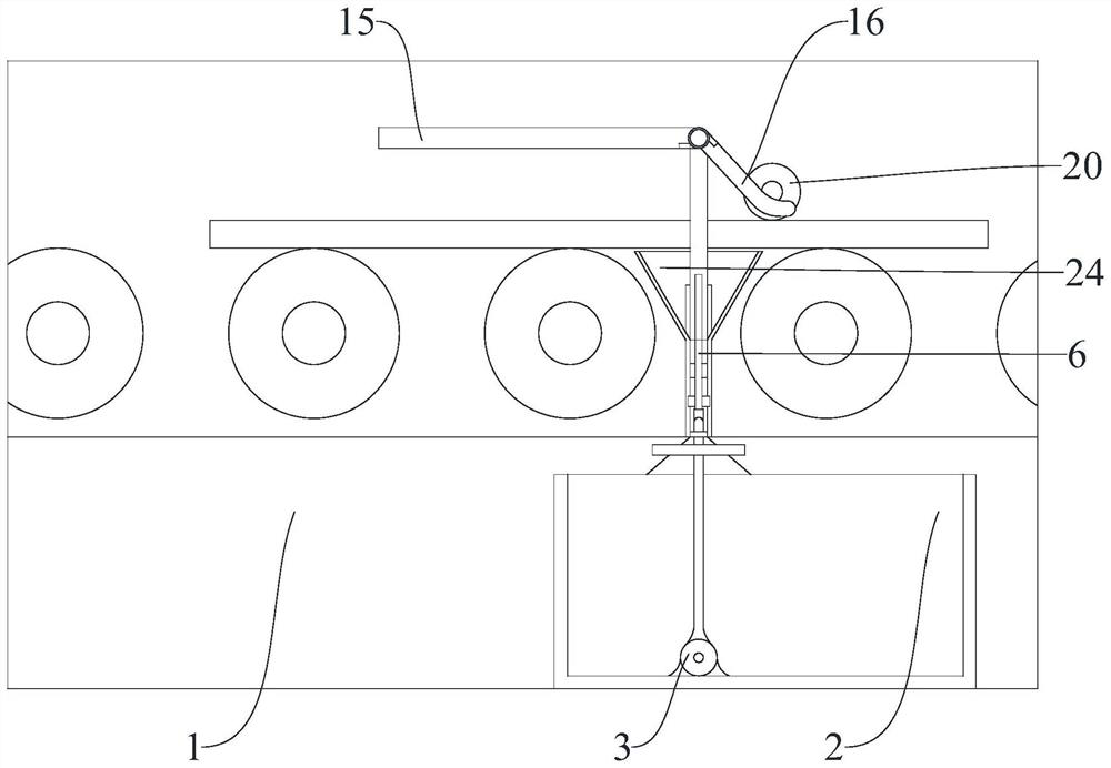
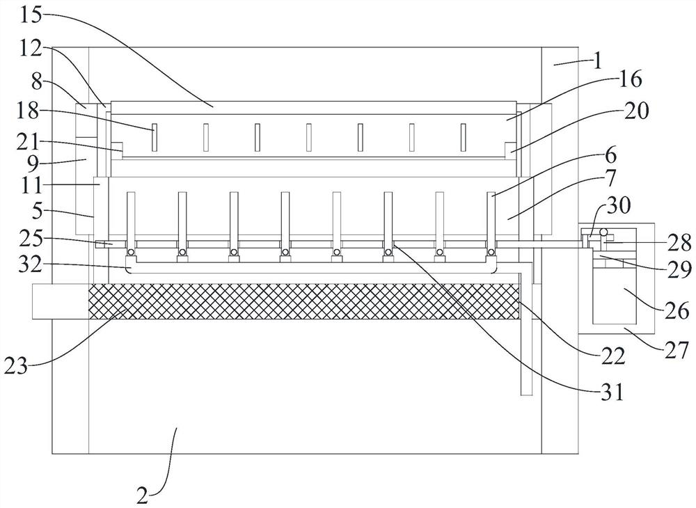
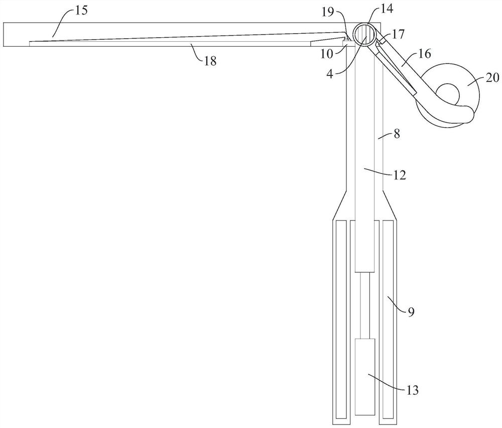
[0027] figure 1 , figure 2 and image 3 A pre-quenching recovery mechanism for a steel plate conveying mechanism shown, including a bottom conveying platform 1 with top support rollers installed on the surface, a bottom liquid storage tank 2 installed inside the bottom conveying platform 1, and a bottom liquid storage tank 2 installed inside the bottom conveying platform 1 The internal electric centrifugal liquid suction pump 3 and electric centrifugal air pump 4, the upper surface of the bottom conveying platform 1 is provided with a bottom storage tank 5 with a built-in longitudinal quenching frame, and a bottom spray nozzle with a built-in movable spray ...


PUM


Abstract

The invention relates to the technical field of steel processing production equipment, in particular to a pre-quenching recovery mechanism for a steel plate conveying mechanism. The pre-quenching recovery mechanism comprises a bottom conveying platform, a bottom liquid storage tank, an electric centrifugal infusion pump and an electric centrifugal air pump. According to the pre-quenching recovery mechanism for the steel plate conveying mechanism, a bottom containing groove internally provided with a longitudinal quenching frame is formed in the upper surface of the bottom conveying platform, a movable spraying nozzle controlled by an adjusting motor is arranged on the inner bottom face of the longitudinal quenching frame, and a spraying range can be greatly widened through overturning in a spraying and quenching process; the height of an upper exhaust frame is adjusted through an electric telescopic push rod, so the exhaust frame is suitable for steel plates of various thicknesses, and an application range is wider; and steam is discharged to the upper surfaces of the steel plates from bottom air outlets in the lower end of a top linkage control frame, so the recycling rate of the steam is greatly improved, and a to-be-sprayed area is pretreated.

Description

technical field [0001] The invention relates to the technical field of steel processing and production equipment, in particular to a pre-quenching recovery mechanism for a steel plate conveying mechanism. Background technique [0002] Steel is a general term for iron-carbon alloys, and steel containing only carbon is called carbon steel or ordinary steel. In actual production, steel often contains different alloying elements according to different uses, such as manganese, nickel, vanadium and so on. [0003] Today, steel is one of the most used materials in the world due to its low price and reliable performance, and it is an indispensable component in construction, manufacturing and people's daily life. It can be said that steel is the material basis of modern society. [0004] In the traditional steel plate production process, in order to facilitate the transfer of the completed steel plate, a large conveying mechanism is required to quench the steel plate during the con...

Claims


Application Information

Patent Timeline
Patent Type & Authority Applications(China)
IPC IPC(8): C21D1/667C21D9/00
CPCC21D1/667C21D9/0081Y02P10/20
Inventor 胡文红陈小祥
Owner 江苏骏茂新材料科技有限公司
Why Eureka
Try Eureka