Winding device for manufacturing composite material NOL ring

A composite material and winding device technology, applied in the field of composite materials, can solve problems such as unfavorable laboratory promotion, expensive equipment, and influence on test results, and achieve the effect of convenient real-time monitoring of winding thickness, avoiding sample damage, and avoiding high prices

Pending Publication Date: 2022-02-22
NO 719 RES INST CHINA SHIPBUILDING IND
View PDF0 Cites 1 Cited by
  • Summary
  • Abstract
  • Description
  • Claims
  • Application Information

AI Technical Summary

Problems solved by technology

The internal pressure vessel formed by filament winding usually adopts the grid theory for strength design. The grid theory only considers the strength and stiffness of the fiber direction, but ignores the effect of the resin. Therefore, for the design of the composite pressure vessel, the annular specimen test Material properties are more meaningful. This kind of annular test piece is usually called NOL ring. At present, the equipment for preparing NOL ring usually uses a large-scale winding machine. First, a long composite material cylinder is prepared, and then it is cut by machining to meet the standard test For a ring with a sample width (6mm, Φ150mm), the cutting process is likely to cause damage to the boundary of the sample, causing some continuous fibers to be cut off, reducing the bearing capacity of the NOL ring, and affecting the test results. In addition, the large-scale winding machine equipment is expensive, Complex control, not conducive to laboratory promotion

Method used


Image

  • Winding device for manufacturing composite material NOL ring
  • Winding device for manufacturing composite material NOL ring

Examples


Embodiment approach 1

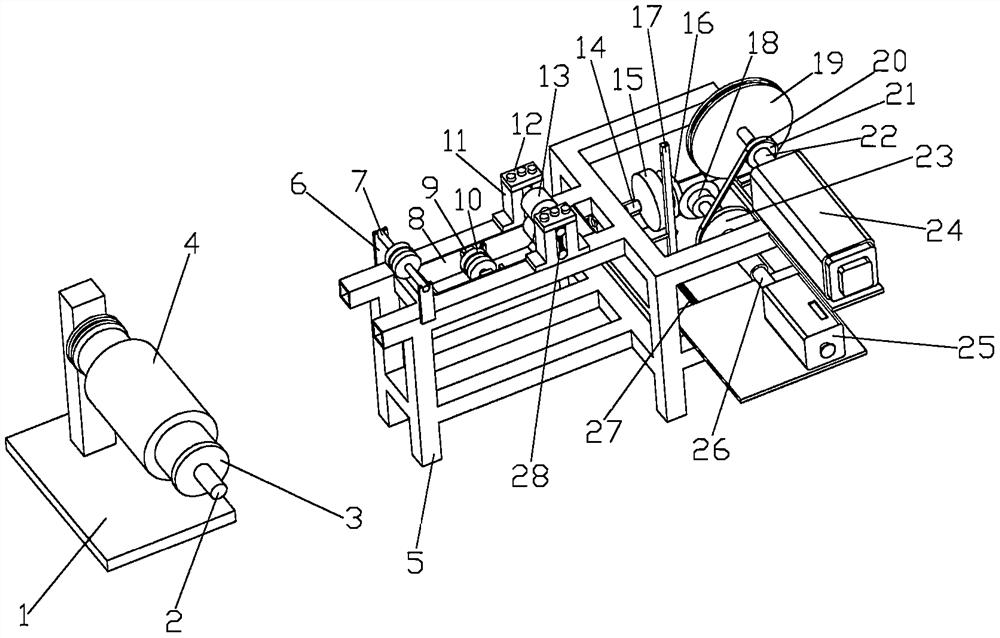
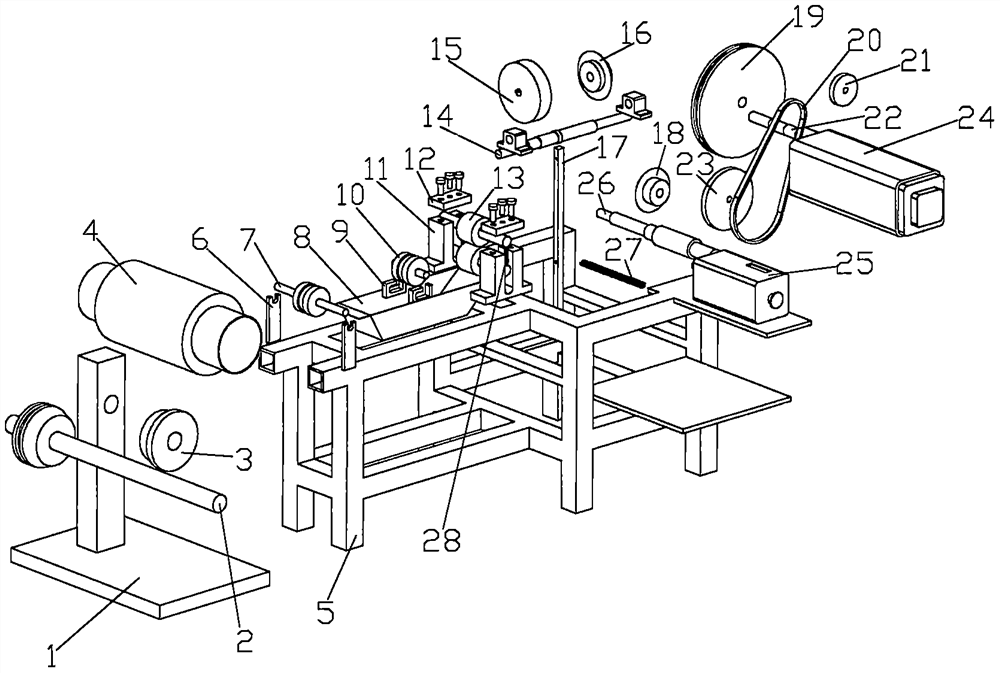
[0027] This embodiment discloses a winding device for making composite NOL rings, which includes a creel (1), a creel shaft (2), a creel shaft sleeve (3), a bobbin (4), and a workbench (5 ), guide roller fixing block (6), yarn guide roller (7), glue tank (8), dipping roller fixing block (9), dipping roller (10), squeezing rubber roller fixing block (11), extrusion Pressing block on the rubber roller (12), extrusion rubber roller (13), shaft three (14), cam (15), bevel gear two (16), thread nozzle light rod (17), bevel gear one (18) , mold (19), belt (20), driving transmission gear (21), shaft one (22), passive transmission gear (23), motor (24), shaft two (26), tension spring (27), compression spring (28).

[0028] The creel (1) is connected to the creel shaft (2) through a bearing, and the bobbin (4) is sleeved on the creel shaft (2).

[0029] In this embodiment, specifically, the creel is a square pillar standing on an iron plate, and a through hole is opened on the upper ...

Embodiment approach 2

[0040] This embodiment discloses a winding device for making composite NOL rings, which includes a creel (1), a creel shaft (2), a creel shaft sleeve (3), a bobbin (4), and a workbench (5 ), guide roller fixing block (6), yarn guide roller (7), glue tank (8), dipping roller fixing block (9), dipping roller (10), squeezing rubber roller fixing block (11), extrusion Pressing block on the rubber roller (12), extrusion rubber roller (13), shaft three (14), cam (15), bevel gear two (16), thread nozzle light rod (17), bevel gear one (18) , mold (19), belt (20), driving transmission gear (21), shaft one (22), passive transmission gear (23), variable speed motor (24), counter (25), shaft two (26), stretch Spring (27), compression spring (28).

[0041] The creel (1) is connected to the creel shaft (2) through a bearing, and the bobbin (4) is sleeved on the creel shaft (2).

[0042] In this embodiment, specifically, the creel is a square pillar standing on an iron plate, a through hol...


PUM


Abstract

The utility model discloses a winding device for manufacturing a composite material NOL ring, which structurally comprises a creel, a creel shaft, a spool, a workbench, a yarn guide roller fixing block, a yarn guide roller, a glue groove, a glue dipping roller fixing block, a glue dipping roller, a glue extruding roller fixing block, a glue extruding roller upper pressing block, a glue extruding roller, a third shaft, a cam, a second bevel gear, a silk nozzle light rod, a first bevel gear, a mold and a belt, a driving transmission gear, a first shaft, a driven transmission gear, a motor, and a second shaft. In the using process, yarn is led out of the spoon (4) and enters the glue groove (8) through the yarn guide roller (7), prepared resin is injected into the glue groove (8), the resin is fully soaked in the glue groove (8) through the glue dipping roller (10), the yarn soaked with the resin passes through the glue extruding roller (13), and redundant resin can be scraped off through a gap of the glue extruding roller (13). And the yarn passing through the rubber extruding roller (13) penetrates through an opening in the upper end of the silk nozzle light rod (17) and is wound on the mold (19), and finally winding of the composite material is completed.

Description

technical field [0001] The invention relates to the field of composite materials, and belongs to a novel winding device for making NOL rings of composite materials. Background technique [0002] Composite winding products have a large number of applications in aerospace, transportation, ships and other fields, including rocket engines, high-pressure gas cylinders, pressure vessels, pipelines, etc. The internal pressure vessel formed by filament winding usually adopts the grid theory for strength design. The grid theory only considers the strength and stiffness of the fiber direction, but ignores the effect of the resin. Therefore, for the design of the composite pressure vessel, the annular specimen test Material properties are more meaningful. This kind of annular test piece is usually called NOL ring. At present, the equipment for preparing NOL ring usually uses a large-scale winding machine. First, a long composite material cylinder is prepared, and then it is cut by mach...

Claims


Application Information

Patent Timeline
IPC IPC(8): B29C70/32B29C70/54
CPCB29C70/32B29C70/54
Inventor 罗锡林魏建辉和卫平李飘傅鑫赖长亮
Owner NO 719 RES INST CHINA SHIPBUILDING IND
Why Eureka
Try Eureka