A dual-fiber matrix coupling chip device

A dual optical fiber and chip technology, applied in the coupling of optical waveguide, optics, light guide, etc., can solve the problems of no coupling device and equipment, failure to effectively detect the proximity state, fragmentation of FA and CHIP, etc., and achieve the realization of the proximity state The effect of monitoring

Active Publication Date: 2022-07-29
QXP TECH INC
View PDF10 Cites 0 Cited by
  • Summary
  • Abstract
  • Description
  • Claims
  • Application Information

AI Technical Summary

Problems solved by technology

[0002] At present, the combination of FA (fiber optic matrix) and a light source on a single PCBA (printed circuit board assembly) or a single CHIP (chip) is a conventional product, and FA+CHIP+FA has not yet appeared and has FIBER TURNING BLOC (jumper steering buckle), so there is no coupling device and equipment that can realize this function
[0003] And the existing FA and CHIP coupling device, the conventional solution is that the tail of a single FA is connected to a jumper through a ceramic ferrule and then directly coupled with CHIP. Effective detection makes it difficult to achieve effective coupling, especially when the coupling needs to be close, too much force will break FA and CHIP

Method used


Image

  • A dual-fiber matrix coupling chip device
  • A dual-fiber matrix coupling chip device
  • A dual-fiber matrix coupling chip device

Examples


Embodiment 1

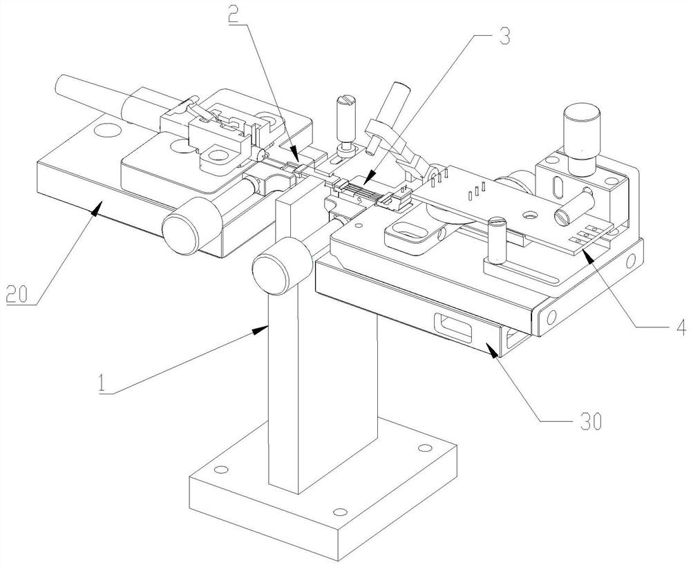
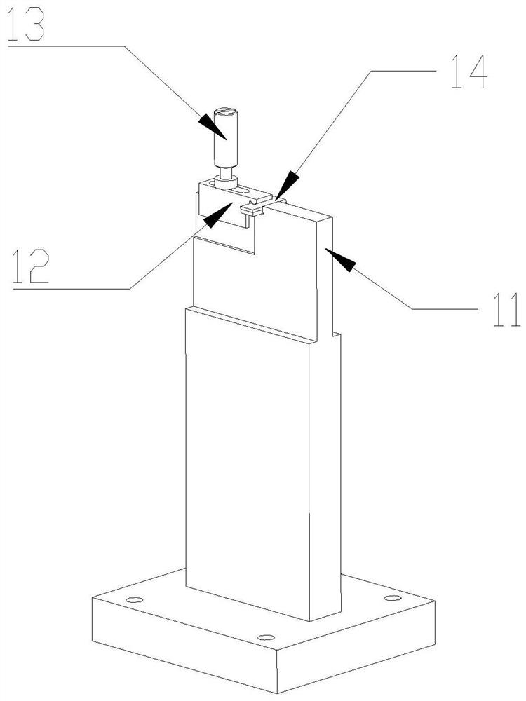
[0078] A dual-fiber matrix coupling chip device, see Figures 1 to 9 shown, including:

[0079] Chip fixing mechanism 1, which fixes the planar waveguide chip 14 thereon;

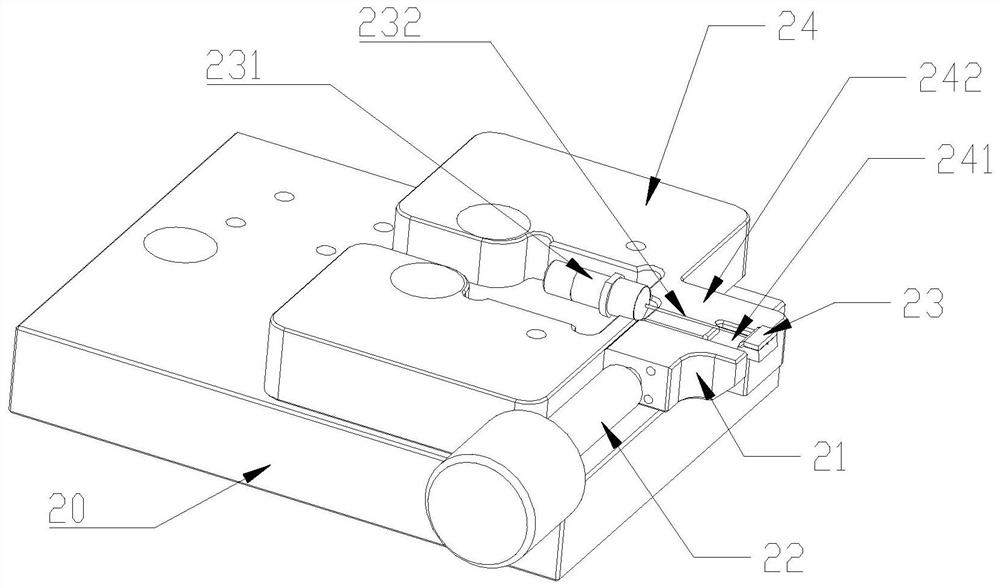
[0080] the first FA clamping mechanism 2, which is arranged on one side of the chip fixing mechanism 1, and is used for clamping the first FA 23 with the first pigtail 232;

[0081] The second FA clamping mechanism 3, which is arranged on the other side of the chip fixing mechanism 1, is used for clamping the second FA33 with the second pigtail;

[0082] Both the first FA clamping mechanism 2 and the second FA clamping mechanism 3 are provided with electric adjustment platforms at the bottom; respectively adjust the two electric adjustment platforms so that the light-transmitting surface of the first FA 23 is parallel to one end face of the chip 14, and The light-transmitting surface of the two FA33 is parallel to the other end surface of the chip 14;

[0083] A first bonding force detection member 20 an...

Embodiment 2

[0105] On the basis of Example 1, see Figure 5 As shown, it also includes an optical power detector 40 and a jumper steering buckle 332;

[0106] The jumper steering buckle 332 is arranged on the second platform 35, and is pressed on the second platform 35 through the board body 34; Turn to vertical delivery fiber. Specifically, one end of the plate body 34 is hinged to one end of the second platform 35 , and the other end of the plate body 34 is provided with a locking knob 341 penetrating through the plate body 34 . The locking knob 341 is connected to the other end of the second platform 35 . screwed. Then, the plate body 34 is pressed against the second platform 35 and the jumper steering buckle 332 is pressed against the second platform 35 at the same time.

[0107] The optical power detector 40 is arranged on the second platform 35 through the positioning connection mechanism 4;

[0108] By adjusting the positioning and connecting mechanism 4, the optical power dete...


PUM


Abstract

The invention provides a dual-fiber matrix coupling chip device, which relates to the field of optoelectronic technology. It includes: a chip fixing mechanism, which is used for fixing the planar waveguide chip; a first FA clamping mechanism, which is arranged on one side of the chip fixing mechanism and used for clamping the first FA with pigtail; the second FA clamping mechanism A mechanism, which is arranged on the other side of the chip fixing mechanism, is used to clamp the second FA with pigtails; the bottom of the first FA clamping mechanism and the second FA clamping mechanism and the electric adjustment platform A first bonding force detection member and a second bonding force detection member are respectively arranged between them. The invention realizes FA+CHIP+FA and has the coupling function of the tail product of FIBERTURNINGBLOC; realizes the proximity state monitoring between FA and CHIP; couples the PD at the tail (in the case that the sensor has a load limit and an external dimension is limited) The adjustment function of multiple positions is realized.

Description

technical field [0001] The invention relates to the field of optoelectronic technology, in particular to a dual-fiber matrix coupling chip device. Background technique [0002] At present, the combination between FA (fiber matrix) and a light source on a single PCBA (printed circuit board assembly) or a single CHIP (chip) is a conventional product, and there is no FA+CHIP+FA with FIBER TURNING BLOC. (Jumper steering buckle), so there is no coupling device and equipment that can realize this function. [0003] And the existing FA and CHIP coupling device, the conventional solution is that the single FA tail is connected to the jumper through the ceramic ferrule and then directly coupled with the CHIP, the close state of the FA and the CHIP between the coupling processes (the strength detection after bonding) fails. Effective detection makes it difficult to achieve effective coupling, especially when the coupling needs to be close, and the force is too large, which will break...

Claims


Application Information

Patent Timeline
Patent Type & Authority Patents(China)
IPC IPC(8): G02B6/42
CPCG02B6/4225G02B6/4226G02B6/4244G02B6/4245
Inventor 谢小飞范修宏徐之光姚宏鹏程东
Owner QXP TECH INC
Why Eureka
Try Eureka