
Transverse flux outer rotor motor

An external rotor motor, transverse magnetic flux technology, applied in the direction of motor, magnetic circuit, electromechanical device, etc., can solve the problems of complex motor stator yoke structure, influence of motor load capacity, reduction of stator magnetic flux, etc., and achieve high stator space utilization. , The effect of increasing the motor torque and increasing the number of motor poles

Active Publication Date: 2022-02-22
山东精创磁电产业技术研究院有限公司
View PDF6 Cites 0 Cited by
  • Summary
  • Abstract
  • Description
  • Claims
  • Application Information

AI Technical Summary

Problems solved by technology

The structure of the motor stator yoke made by this method is complicated, the manufacture is difficult, and the space is wasted. It is difficult to achieve a perfect connection between the magnetic flux on the stator teeth on both sides of the coil and the yoke. The stator flux is reduced, the load capacity of the motor will be affected, and the output of the motor will be limited

Method used


Image

  • Transverse flux outer rotor motor
  • Transverse flux outer rotor motor
  • Transverse flux outer rotor motor

Examples


example 1

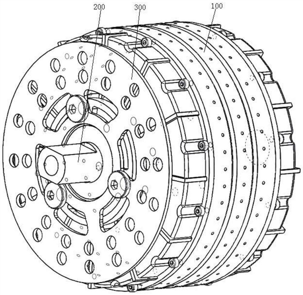
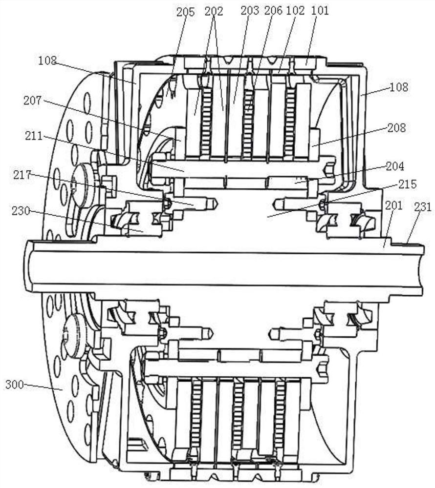
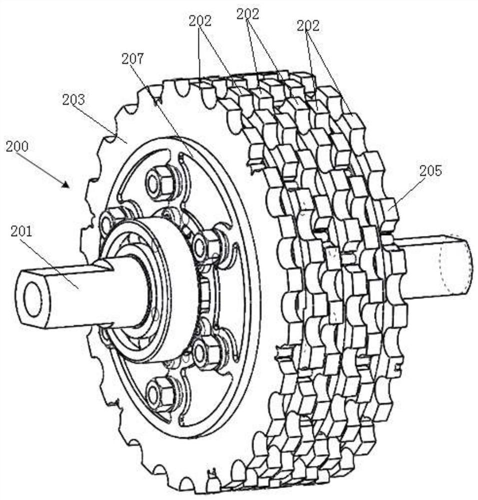
[0080] In this example, for example image 3 , 4 , 11-13, the first side plate 207 and the second side plate 208 are symmetrical in shape, the first side plate 207 and the second side plate 208 are provided with a third set of bolt holes 214, and the stator shaft 201 is provided with A plurality of protruding structures 215, the outer surface of the protruding structure 215 is in contact with the inner circle of the stator yoke ring 204, a fourth group of bolt holes 216 are opened on both sides of the protruding structure 215, and the second group of bolts 217 pass through the first The three sets of bolt holes 214 and the fourth set of bolt holes 216 connect the first side plate 207 and the second side plate 208 to the two sides of the protruding structure 215 respectively.

[0081] In this example, two side plates are used to clamp the multi-phase stator module, and the first set of bolts are passed through the multi-phase stator module to secure the first set of bolts to t...

example 2

[0088] In this example, for example Figure 14-17 As shown, the first side plate 207 is integrated with the stator shaft 201, and the outer surface of the stator shaft 201 is in contact with the inner circle of the stator yoke ring 204; one side of the second side plate 208 is pressed on the stator tooth plate 203, and the other A weight reducing groove 218 is provided on the side, an inward positioning block 221 is provided on the inner circle of the second side plate 208 , and a positioning groove 222 is provided on the stator shaft 201 .

[0089] The stator shaft 201 is a hollow shaft, the stator shaft 201 is provided with an outlet slot 223, the two ends of the stator shaft 201 are provided with a positioning plane 231, and the two ends of the stator shaft 201 are arranged on an arc 233 outside the positioning plane 231. thread.

[0090] The difference between this example and Example 1 is that the structures of the first side plate, the second side plate and the stator s...

example 3

[0093] In this example, for example Figure 18-24 As shown, the middle part of the first side plate 207 and the second side plate 208 is sunken toward the middle part of the stator shaft, the first side plate 207 is fixed on the stator shaft 201 by a third set of bolts 224, and the second side plate 208 is fixed by the shaft The sleeve 225 is fixed on the stator shaft 201 , and there is a space between the outer surface of the stator shaft 201 and the inner circle of the stator yoke ring 204 .

[0094] The first side plate 207 is provided with a fifth group of bolt holes 226 in the recess, and the stator shaft 201 is provided with a plurality of protruding sheet structures 227, and the sheet structure 227 is provided with a sixth group of bolt holes 228, and the third group Bolts 224 pass through the fifth set of bolt holes 226 and the sixth set of bolt holes 228 to fix the first side plate 207 on the stator shaft 201 .

[0095] The shaft sleeve 225 is welded on the inner cir...


PUM


Abstract

The invention discloses a transverse flux outer rotor motor, and belongs to the field of motors. The motor comprises an outer rotor assembly and a stator assembly. The stator assembly comprises a stator shaft and multi-phase stator modules, each phase of stator module comprises two stator toothed plates and a stator yoke ring, and a coil wound around the axial direction as the center is arranged between the two stator toothed plates. The outer rotor assembly comprises a rotor yoke ring, the inner surface of the rotor yoke ring is provided with a plurality of rows of magnetic steel distributed in the axial direction, the number of the rows of the magnetic steel is the same as the number of phases of the stator modules, the magnetizing direction of the magnetic steel is the radial direction, and the number of the magnetic steel in each row is two times of the number of stator teeth on one stator toothed plate. The magnetic field directions of the two adjacent magnetic steels in each row are opposite, and the magnetic field directions of the two adjacent magnetic steels in the adjacent row are the same. A three-dimensional magnetic circuit structure is realized by combining the silicon steel sheet stator toothed plates and the SMC stator yoke ring, the manufacturing difficulty is low, the working time and the cost are low, the coil winding is convenient, more poles can be manufactured, and the torque pulsation of the motor is reduced.

Description

technical field [0001] The invention relates to the field of motors, in particular to a transverse magnetic flux outer rotor motor. Background technique [0002] The transverse flux motor is different from the radial flux motor and the axial flux motor of the traditional structure. The magnetic force lines inside the transverse flux motor are three-dimensionally distributed and have a high torque density. The outer rotor transverse flux motor is a structural form of the transverse flux motor, which is generally used in the hub motor of electric vehicles. [0003] The traditional in-wheel motor is generally an outer rotor radial flux motor, the rotor of which is easy to manufacture, but the winding of the stator is relatively difficult. Each phase of the outer rotor radial flux motor has multiple slots in the circumferential direction, and each slot is individually embedded when winding the coil. Such a winding method is more complicated, especially when the motor has a larg...

Claims


Application Information

Patent Timeline
Patent Type & Authority Applications(China)
IPC IPC(8): H02K1/02H02K1/12H02K1/18H02K1/2789H02K5/04H02K11/01
CPCH02K1/02H02K1/12H02K1/182H02K1/2786H02K5/04H02K11/01H02K2201/12H02K2213/12Y02T10/64
Inventor 李树才孙蕾张文晶张再成赵孔祥
Owner 山东精创磁电产业技术研究院有限公司
Learn More