
Anti-infection joint occupying device

An anti-infection and joint technology, applied in elbow joints, knee joints, joint implants, etc., can solve the problems of knee joint dislocation, small flexion angle of placeholders, hard antibiotic bone cement, etc., to prevent fracture and to install quickly. The effect of firmness and toughness improvement

Inactive Publication Date: 2022-02-25
LUOYANG ORTHOPEDIC TRAUMATOLOGICAL HOSPITAL
View PDF0 Cites 0 Cited by
  • Summary
  • Abstract
  • Description
  • Claims
  • Application Information

AI Technical Summary

Problems solved by technology

However, the friction surface of the existing spacer (the contact surface between the femoral end and the tibial end spacer) is usually a cylindrical surface. Such a design can only realize the bending movement of the knee joint around a fixed rotation axis, and it is difficult to make small left and right movements. Swing, intuitively, it is difficult for the patient to swing the calf left and right after implanting the traditional spacer, and can only swing the calf back and forth
Usually, after the knee prosthesis is removed, the ligaments of the knee joint are usually loose and damaged to varying degrees. Because the commonly used antibiotic bone cement is hard and brittle, the existing spacers have no effective limit design. , the patient's large leg movements may cause the knee joint to dislocate, and the distal femur slides forward out of the tibial plateau
The spacer is easy to loosen, and the risk of recurrence of infection is increased after loosening, and the flexion angle of the traditional spacer is usually small, which can only ensure a small range of knee joint movement for the patient

Method used


Image

  • Anti-infection joint occupying device
  • Anti-infection joint occupying device
  • Anti-infection joint occupying device

Examples


Embodiment Construction

[0027] The following will clearly and completely describe the technical solutions in the embodiments of the present invention with reference to the accompanying drawings in the embodiments of the present invention. Obviously, the described embodiments are only some, not all, embodiments of the present invention. Based on the embodiments of the present invention, all other embodiments obtained by persons of ordinary skill in the art without making creative efforts belong to the protection scope of the present invention.

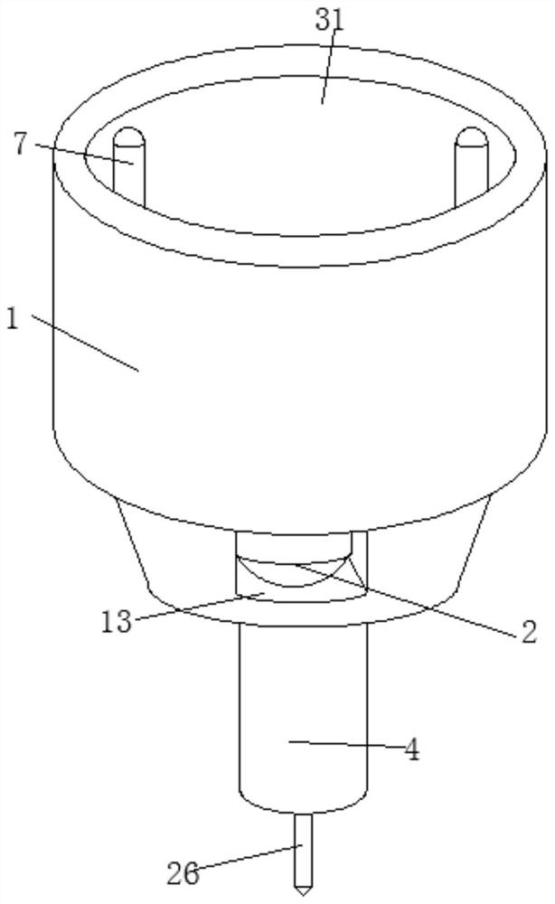
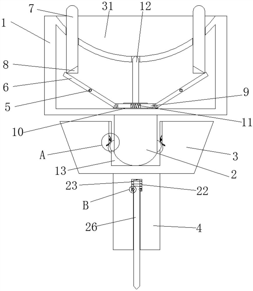
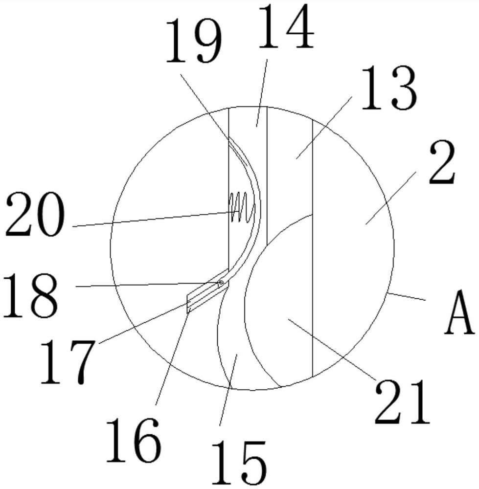
[0028] Such as Figure 1-5 As shown, the present invention provides a technical solution: an anti-infection joint space occupying device, comprising a femoral joint 1, a connecting piece 2 is fixed at the bottom of the femoral joint 1, a femoral groove 31 is opened on the upper surface of the femoral joint 1, and a femoral joint 1 is provided. A tibial joint 3 is arranged below the joint 1, a fixed column 4 is fixed at the bottom of the tibial joint 3, two fix...


PUM


Abstract

The invention relates to the technical field of medical instruments, and discloses an anti-infection joint occupying device. The device comprises a thighbone joint piece, a connecting piece is fixed to the bottom of the thighbone joint piece, a thighbone groove is formed in the upper surface of the thighbone joint piece, a tibia joint piece is arranged below the thighbone joint piece, a fixing column is fixed to the bottom of the tibia joint piece, two fixing shafts are fixed in the thighbone joint piece, rotating rods are rotatably connected to the outer surfaces of the two fixing shafts, telescopic rods are rotatably connected to the bottoms of the rotating rods, and a transverse cylinder is arranged on the outer surfaces of the two telescopic rods in a sleeving mode. By arranging the thighbone joint piece and the tibia joint piece, the connecting piece of the thighbone joint piece is matched with the connecting groove of the tibia joint piece, so that the knee joint of a patient is prevented from rotating and dislocation in the horizontal direction after operation; and by arranging structures such as a movable rod and an elastic piece, the device can enable the shank to swing left and right in a small range while the shank can swing back and forth freely after the occupying device is implanted into the patient.

Description

technical field [0001] The invention relates to the technical field of medical devices, in particular to an anti-infection joint space occupying device. Background technique [0002] Peripsthetic infection after total knee arthroplasty is a disastrous complication after knee arthroplasty. According to statistics, the incidence of prosthetic infection worldwide is between 1-2%, but periprosthetic infection is the primary factor of total knee arthroplasty failure (accounting for about 25% of failure cases). The standard treatment for periprosthetic knee prosthetic infections is a two-stage revision, through which good long-term results can be obtained in 90% of cases. To ensure maximum sterility and sustained release of antibiotics, placeholders are usually fabricated on-site during surgery, and common methods include handcrafting and traditional mold casting. However, the friction surface of the existing spacer (the contact surface between the femoral end and the tibial end...

Claims


Application Information

Patent Timeline
Patent Type & Authority Applications(China)
IPC IPC(8): A61F2/38
CPCA61F2/3836A61F2/3854
Inventor 陈江非王静趟艳锋
Owner LUOYANG ORTHOPEDIC TRAUMATOLOGICAL HOSPITAL
Learn More