Peritoneal dialysis device facilitating waste liquid treatment

A peritoneal dialysis and waste fluid technology, applied in peritoneal dialysis, dialysis systems, suction devices, etc., can solve problems such as troublesome operation, heating of dialysate, etc., and achieve the effects of good disinfection treatment and simple operation.

Inactive Publication Date: 2022-02-25
PEOPLES HOSPITAL OF HENAN PROV
View PDF1 Cites 0 Cited by
  • Summary
  • Abstract
  • Description
  • Claims
  • Application Information

AI Technical Summary

Problems solved by technology

[0006] In order to overcome the disadvantages of the above-mentioned patent that medical personnel need to frequently replace the waste liquid bag, the operation is troublesome, and the dialysate in the dialysis bag cannot be heated, the technical problem to be solved by the present invention is to provide a simple operation that can A peritoneal dialysis device that heats the dialysate in the dialysis bag to facilitate waste liquid disposal

Method used


Image

  • Peritoneal dialysis device facilitating waste liquid treatment
  • Peritoneal dialysis device facilitating waste liquid treatment
  • Peritoneal dialysis device facilitating waste liquid treatment

Examples


Embodiment 1

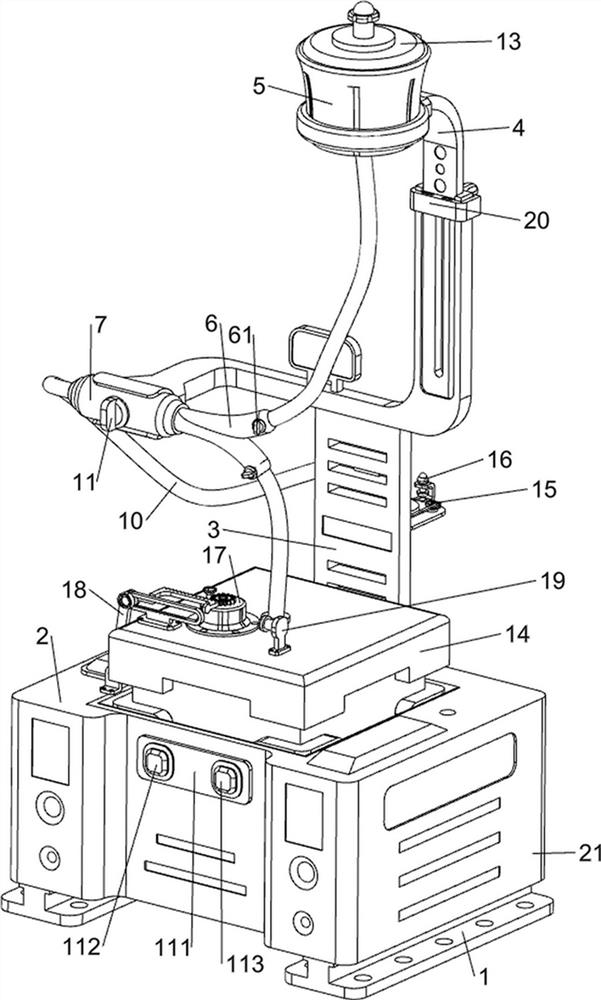
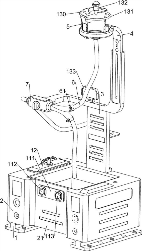
[0045] A peritoneal dialysis device that facilitates waste disposal, such as figure 1 , figure 2 , Figure 18 and Figure 19 As shown, it includes a load-bearing frame 1, a constant temperature box 2, a housing 21, a support frame 3, a lifting block 4, a blanking frame 5, a v-shaped tube 6, a switch valve 61, a connector 7, a support block 8, and a connecting plate 81 , connecting pipe 9, connecting pipe 10, valve 11, control box 111, start switch 112, changeover switch 113, cover plate 12, heating mechanism 13 and collecting mechanism 14, the left side of housing 21 is connected with thermostat 2, thermostat 2 is used to heat the dialysate in the dialysis bag. A load-bearing frame 1 is connected to the bottom of the incubator 2 and the right side of the bottom of the housing 21, and the support frame 3 is connected to the rear side of the top of the housing 21 by bolts. The upper part of the frame 3 is slidingly connected with a lifting block 4, and the upper part of the ...

Embodiment 2

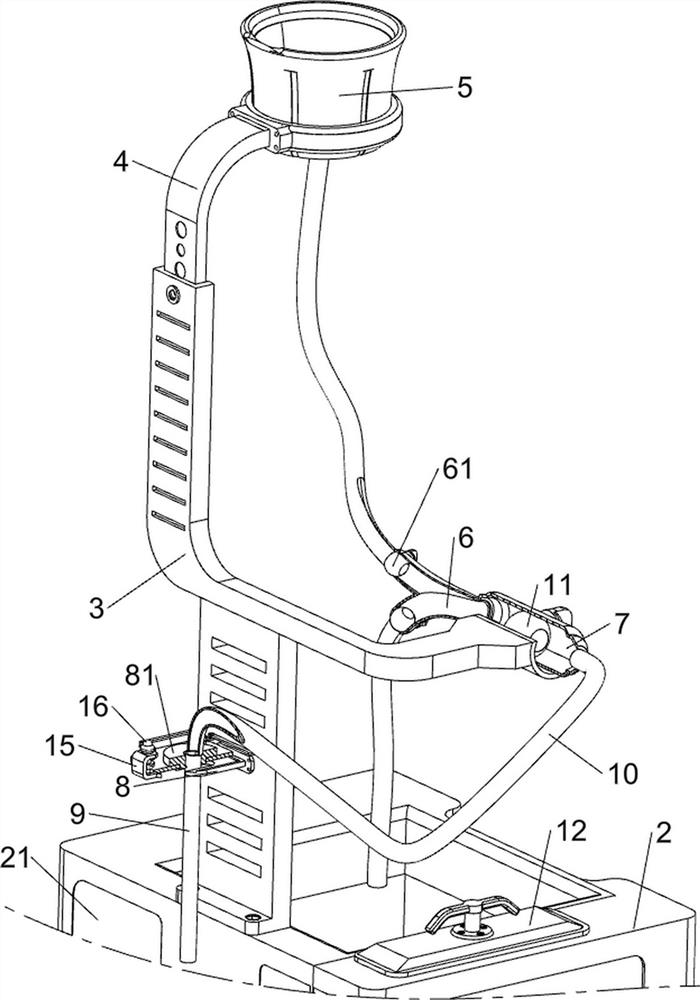
[0050] On the basis of Example 1, such as figure 1 , Figure 5 , Figure 6 , Figure 7 , Figure 18 and Figure 19As shown, an adsorption mechanism 15 is also included, and the connection plate 81 is provided with an adsorption mechanism 15. The adsorption mechanism 15 is used to fix the connection plate 81 on the skin of the patient's abdomen to prevent the connecting tube 9 from slipping out of the patient's body. The adsorption mechanism 15 includes Suction cup 150, rotating shaft 151, second piston 152, back-moving spring 153, first connection block 154, distance sensor 155, buzzer 156 and rotation block 157, are connected with four suction cups 150 at intervals on the connection plate 81, four suction cups A rotating shaft 151 is connected in a rotating and sliding manner in 150, and a second piston 152 is connected to the bottom ends of the four rotating shafts 151. Both are provided with two ventilating grooves capable of ventilation, and the ventilating grooves ca...

Embodiment 3

[0053] On the basis of Example 2, such as figure 1 , Figure 8 , Figure 9 , Figure 18 and Figure 19 As shown, a rotating mechanism 16 is also included. A rotating mechanism 16 is provided between the connecting plate 81 and the rotating shaft 151. The rotating mechanism 16 is used to drive the four rotating shafts 151 to rotate simultaneously. The rotating mechanism 16 includes a telescopic frame 160, a sliding rod 161, return force spring 162, electromagnet 163, iron block 164, the first swing bar 165 and control switch 166, connecting plate 81 top left side is connected with telescoping frame 160, and telescopic frame 160 is connected with sliding bar 161 in sliding type, and sliding bar 161 is slidably connected with an iron block 164, and the sliding rod 161 is covered with a return force spring 162. One end of the return force spring 162 is connected with the iron block 164, and the other end of the return force spring 162 is connected with the slide bar 161. A fir...


PUM


Abstract

The invention relates to a peritoneal dialysis device, in particular to a peritoneal dialysis device facilitating waste liquid treatment. The peritoneal dialysis device facilitating waste liquid treatment comprises a shell, a supporting frame, a lifting block, a discharging frame, a v-shaped pipe, a connector and the like, the supporting frame is connected to the rear side of the top of the shell, the lifting block is slidably connected to the upper portion in the supporting frame, the discharging frame is connected to the upper portion in the lifting block, and the connector is clamped to the front side in the supporting frame. The v-shaped pipe is connected to the right side of the connector, and one end of the v-shaped pipe penetrates through the bottom of the discharging frame and is connected with the bottom of the discharging frame in a clamped mode. A constant-temperature box can heat dialysate in a dialysis bag, an electric heating pipe can heat the dialysate in the dialysis bag in the discharging frame, the temperature of the dialysate is kept close to the body temperature of a patient, a collecting frame can collect more waste liquid at a time, therefore, medical staff do not need to frequently replace the waste liquid bag, and operation is easy.

Description

technical field [0001] The invention relates to a peritoneal dialysis device, in particular to a peritoneal dialysis device which is convenient for treating waste liquid. Background technique [0002] Peritoneal dialysis is a dialysis method that uses the body's own peritoneum as a dialysis membrane. The dialysate poured into the peritoneal cavity exchanges solutes and water with the plasma components in the capillaries on the other side of the peritoneum to remove metabolites and Excessive water, at the same time supplement the necessary substances of the body through the dialysis fluid, and constantly update the peritoneal dialysis fluid to achieve the purpose of kidney replacement or supportive treatment. [0003] After retrieval, the patent publication number is: CN206151969U patent, a peritoneal dialysis device that avoids catheter drift. The peritoneal dialysis device comprises a peritoneal dialysis bag, a waste liquid bag, a peritoneal dialysis external short tube, a...

Claims


Application Information

Patent Timeline
Patent Type & Authority Applications(China)
IPC IPC(8): A61M1/28
CPCA61M1/28A61M1/287
Inventor 李红艳李耀南李静宇
Owner PEOPLES HOSPITAL OF HENAN PROV
Why Eureka
Try Eureka