
Intubation device capable of being used for difficult airway independently or in cooperation with fiber bronchoscope

A fiberoptic bronchoscope, a difficult technology, applied in the field of medical endoscopy, can solve the problems of not being able to expose the glottis or even the epiglottis, failure of intubation, provoking the epiglottis, etc., and achieve the effect of flexible use, small overall thickness and thin structure

Pending Publication Date: 2022-02-25
罗和国
View PDF0 Cites 0 Cited by
  • Summary
  • Abstract
  • Description
  • Claims
  • Application Information

AI Technical Summary

Problems solved by technology

[0004] The purpose of the present invention is to provide an intubation device that can be used alone or in conjunction with a fiberoptic bronchoscope for difficult airways. For patients who cannot insert a fiberoptic bronchoscope from the nasopharynx (for example, patients with nasopharyngeal carcinoma or patients with nosebleeds or easily injured nasal mucosa) or endotracheal tubes can only be intubated from the mouth. The laryngoscope and the laryngoscope used with it are relatively large in size and have a large curvature. As a result, the laryngoscope cannot pass through the base of the tongue, provoke the epiglottis, and even encounter some patients with limited mouth opening. It can’t be put into the mouth, or it can barely enter the mouth, and the glottis or even the epiglottis cannot be exposed. The airway can only be established through difficult airway tools such as fiberoptic bronchoscopes. No force, unable to pass through the base of the tongue, exposing the glottis, and even the epiglottis, easily slipping into the esophagus, resulting in failure of intubation

Method used


Image

  • Intubation device capable of being used for difficult airway independently or in cooperation with fiber bronchoscope
  • Intubation device capable of being used for difficult airway independently or in cooperation with fiber bronchoscope
  • Intubation device capable of being used for difficult airway independently or in cooperation with fiber bronchoscope

Examples


Embodiment 1

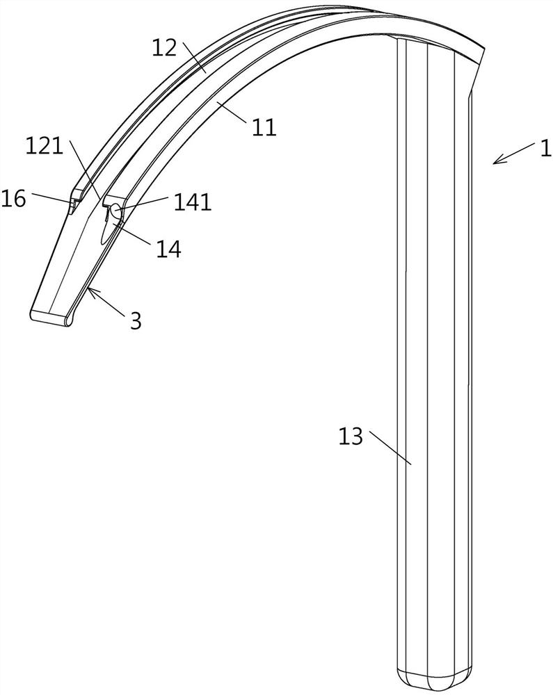
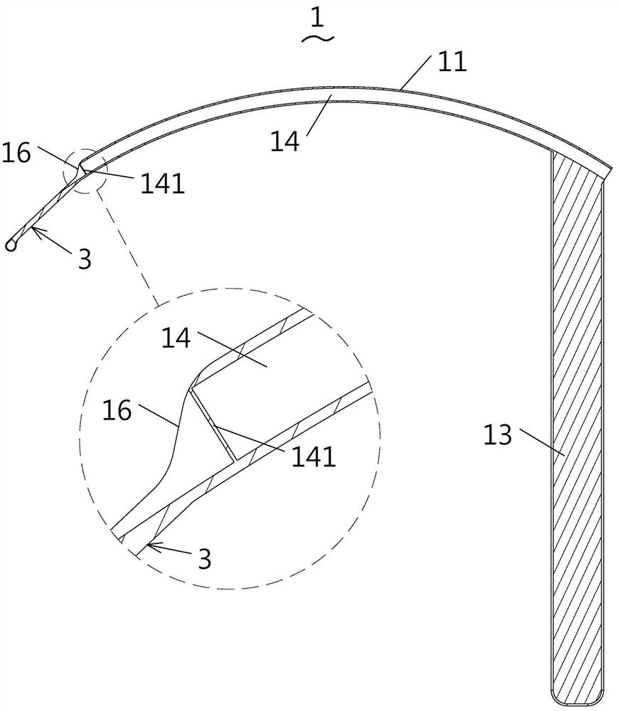
[0034] Embodiment one: if Figure 1-2 As shown in , an intubation device that can be used alone in a difficult airway includes an insertion guide rail 1, and the insertion guide rail 1 includes a guide rail main body 11 in the shape of a circular arc strip, and the guide rail main body 11 is axially The upper width is 12 mm, the radial thickness of the guide rail body 11 is 4 mm, and the outer circular arc surface of the guide rail body 11 extends in the upper direction to provide a T with two ends respectively penetrating the two ends of the guide rail body 11 in the circumferential direction. Type guide slot 12, the groove bottom width of described T-type guide slot 12 is 7.5mm, the notch of described T-type guide slot corresponds to the width in the axial direction is 5.5mm, also on described rail main body 11 Extending in the circumferential direction, there is a video channel 14 that runs through both ends of the guide rail body 11 in the circumferential direction. A tra...

Embodiment 2

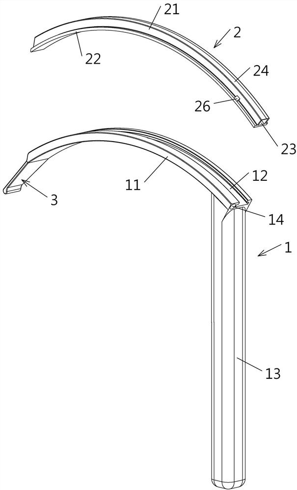
[0036] Embodiment two: if Figure 1-7 As shown, an intubation device for a difficult airway with a fiberoptic bronchoscope includes an insertion guide rail 1 and an insertion catheter 2. The insertion guide rail 1 includes a guide rail main body 11 in the shape of a circular arc strip. The width of the main body 11 in the axial direction is 12 mm, the radial thickness of the guide rail main body 11 is 4 mm, and the outer circular arc surface of the guide rail main body 11 is provided with two ends extending through the guide rail main body 11 respectively. The T-shaped guide slots 12 at both ends in the circumferential direction, the groove bottom width of the T-shaped guide slot 12 is 7.5mm, and the notch of the T-shaped guide slot corresponds to a width of 5.5mm in the axial direction. The guide rail main body 11 also extends circumferentially with a video channel 14 that runs through both ends of the guide rail main body 11 in the circumferential direction. Arranged side b...

Embodiment 3

[0039] Embodiment three: as Figure 8-9 As shown, on the basis of Embodiments 1 and 2, the tongue depressor 3 is hinged to one end of the guide rail body 11 in the circumferential direction, and a threading hole is provided on the side of the guide rail body 11 close to the inner arc surface. 15. The inner diameter of the threading tunnel 15 is 0.5 mm, one end of the threading tunnel 15 extends circumferentially to one end of the operating handle 13 that runs through the guide rail main body 11, and the other end of the threading tunnel 15 One end extends circumferentially until one end of the tongue depressor 3 is hinged, and then deflects radially inwardly to pass through the inner arc surface of the guide rail main body 11. A pull wire 31 is threaded through the threading tunnel 15, and the pull wire The diameter of 31 is matched with the threading channel 15. The stay wire 31 is preferably a steel wire. One end of the stay wire 31 is connected to the lower side of the spat...


PUM

PropertyMeasurementUnit
Widthaaaaaaaaaa
Radial thicknessaaaaaaaaaa
Chord lengthaaaaaaaaaa

Abstract

The invention provides an intubation device capable of being used for a difficult airway independently or in cooperation with a fiber bronchoscope. The intubation device comprises an insertion guide rail, the insertion guide rail comprises a guide rail main body in a circular arc strip shape, and a T-shaped guide slot penetrating through the two circumferential ends of the guide rail main body is formed in the outer circular arc surface of the guide rail main body in a circumferential extending mode; the guide rail main body is further provided with a video hole channel which extends in the circumferential direction and penetrates through the two ends of the guide rail main body in the circumferential direction, and a transparent lens is embedded in one port of the video hole channel; a tongue depressor is connected to one end, corresponding to the embedded transparent lens, of the guide rail main body, and an operating handle is fixedly arranged at the other end, located on the inner arc surface, of the guide rail main body in the circumferential direction; and a guide marking line extending to the two ends is carved on the groove bottom wall of the T-shaped guide slot. The device is small in overall thickness, and can be used by patients with difficult airways under various conditions such as small opening degrees.

Description

technical field [0001] The invention relates to the technical field of medical endoscopy, in particular to a device for using an electronic video bronchoscope for tracheal intubation and throat diagnosis and treatment, specifically a device that can be used alone or in conjunction with a fiberoptic bronchoscope for difficult airways Intubation device. Background technique [0002] Since Cahersa, Spain invented the world's first laryngoscope in 1855, various new types of laryngoscopes have emerged. With the development of technology, in 2001, the Canadian Saturn company invented the Glidescope video laryngoscope, which revolutionized the way of tracheal intubation or laryngeal diagnosis and treatment. Therefore, video laryngoscope has been widely promoted and applied rapidly all over the world. In clinical medicine, before anesthesiologists use anesthesia machines, ventilators and other equipment for patients, they generally need to perform tracheal intubation on patients, ...

Claims


Application Information

Patent Timeline
IPC IPC(8): A61M16/04A61B1/00A61B1/04A61B1/06A61B1/267
CPCA61M16/0402A61M16/0463A61M16/0465A61B1/00131A61B1/04A61B1/06A61B1/267A61M2205/583A61M2205/587
Inventor 蔺琳罗和国
Owner 罗和国
Learn More