Turnover type laser welding machine clamping mechanism and working method thereof
A technology of laser welding machine and clamping mechanism, applied in laser welding equipment, welding equipment, manufacturing tools, etc., can solve the problems of low efficiency, difficult to clamp multiple workpieces to be processed, etc., and achieve the effect of improving efficiency
- Summary
- Abstract
- Description
- Claims
- Application Information
AI Technical Summary
Problems solved by technology
Method used
Image

Examples
Embodiment 1
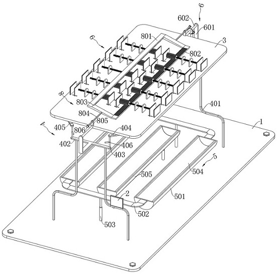
[0102] see Figure 1-Figure 15 , the present invention provides the following technical solutions:
[0103] A clamping mechanism of a reversible laser welding machine, comprising:
[0104] Base 1, on the upper side of the base 1 is provided with a console 3
[0105] see figure 1 , figure 2 and Figure 15 , there is a supporting mechanism 4 between the base 1 and the console 3, which supports the console 3 in an adjustable manner to increase the stability. The supporting mechanism 4 is provided with two groups, and the two groups of supporting mechanisms 4 are symmetrically arranged between the Between the consoles 3, wherein each set of support mechanisms 4 is composed of a fixed support assembly and a rotating support assembly, specifically as follows:
[0106] read on figure 1 , figure 2 , Figure 14 and Figure 15 , the fixed support assembly is located on the top of the base 1, specifically: each set of fixed support assemblies includes a special-shaped support ...
Embodiment 2
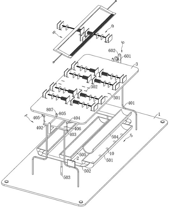
[0143] In Example 1, after turning over, when the lower clamping is performed, the upper clamped and welded workpiece will fall, so it needs to be collected. Similarly, after turning over again, when the upper clamping is performed, the lower clamping and welding The welded workpiece will fall again, and it also needs to be collected here. How to realize automatic and separate collection, embodiment 2 is further optimized on the basis of embodiment 1:
[0144] see Figure 1-Figure 15 , the collection mechanism 5 is located on the base 1 and is located on the lower side of the console 3, which is used to collect the workpiece clamped or clamped below;
[0145] The signal transmission mechanism 11 is arranged on the positioning mechanism 7, and it is used for signal transmission;
[0146] The vibration sensor 10 is located on the material collecting mechanism 5, and it is used for signal transmission; and
[0147] The PLC controller 2 is set on one of the special-shaped suppor...
Embodiment 3
[0160] A working method of a clamping mechanism of a reversible laser welding machine, comprising the following steps:
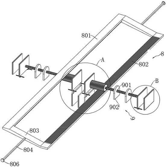
[0161] S1. Upper clamping: Loosen the two positioning nuts 807 in turn, place multiple identical workpieces to be processed between the two groups of upper clamping fixed plate 9010 and upper clamping moving plate 9011, and pull the handle 806 outward , and then drive the first rack 801 and the second rack 802 to move linearly through the rectangular slider 804 and the connecting bar 803. The two sets of extrusion gears 903 are then driven to rotate and move outward along the tooth tracks of the first rack 801 and the second rack 802, and the two sets of extrusion gears 903 respectively drive two sets of screws. 901 rotates and moves to the outside, and then gradually squeezes the two groups of upper clamping movable plates 9011 and drives them close to the upper clamping fixed plate 9010 until the upper clamping of the workpiece to be processed is realized;...
PUM
 Abstract
Description
Claims
Application Information
 - R&D
- Intellectual Property
- Life Sciences
- Materials
- Tech Scout
- Unparalleled Data Quality
- Higher Quality Content
- 60% Fewer Hallucinations
Browse by: Latest US Patents, China's latest patents, Technical Efficacy Thesaurus, Application Domain, Technology Topic, Popular Technical Reports.
© 2025 PatSnap. All rights reserved.Legal|Privacy policy|Modern Slavery Act Transparency Statement|Sitemap|About US| Contact US: help@patsnap.com