Fuel cell liquid water self-adaptive flow field plate capable of automatically switching between parallel flow field and snakelike flow field

A fuel cell and self-adaptive flow technology, which is applied to fuel cells, circuits, electrical components, etc., can solve the problems of increased pump power consumption, large pressure drop, and increased two-phase flow resistance, so as to reduce pump power consumption, Avoid local flooding and reduce flow resistance

Active Publication Date: 2022-02-25
BEIJING UNIV OF TECH
View PDF14 Cites 0 Cited by
  • Summary
  • Abstract
  • Description
  • Claims
  • Application Information

AI Technical Summary

Problems solved by technology

[0004] At present, researchers have optimized the size of the parallel flow field from the channel depth, width, ridge width, etc., and added stoppers in the channel to promote mass transfer and accelerate liquid water removal, but adding stoppers will increase the two-phase flow The optimization of the serpentine flow field lies in the optimization of the number of flow channels and corner design. Although these optimizations have improved the performance of the fuel cell in the serpentine flow field, the problems of large pressure drop and increased pump power consumption are still unresolved. get well resolved

Method used


Image

  • Fuel cell liquid water self-adaptive flow field plate capable of automatically switching between parallel flow field and snakelike flow field
  • Fuel cell liquid water self-adaptive flow field plate capable of automatically switching between parallel flow field and snakelike flow field
  • Fuel cell liquid water self-adaptive flow field plate capable of automatically switching between parallel flow field and snakelike flow field

Examples


Embodiment Construction

[0025] Below in conjunction with accompanying drawing and case the specific embodiment of the present invention is described further:

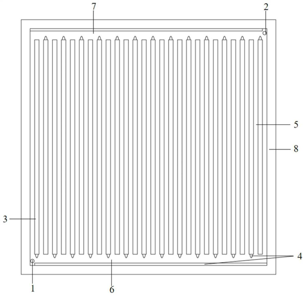
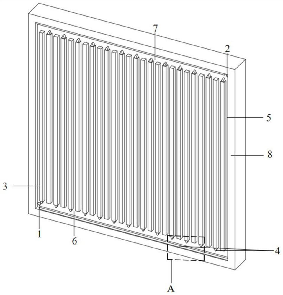
[0026] Such as figure 1 with figure 2 As shown, adaptive structures 4 are arranged on both sides of the main inlet pipe 6 and the main outlet pipe 7, so that the flow field has a certain ability to adapt to liquid water. The reactant enters the inlet manifold 6 from the inlet 1 of the cathode and anode plates respectively, and then enters the flow channel 5 formed between adjacent ridges 3 , collects in the outlet manifold 7 , and flows out from the outlet 2 . During the whole flow process, the reaction gas is transported to the catalytic layer through the diffusion layer for electrochemical reaction, and the generated liquid water enters the flow channel 5, the inlet main pipe 6 and the outlet main pipe 7 through the diffusion layer. When the liquid water passes through the self-adaptive structure 4 on the side of the ridge 3 along with th...


PUM

PropertyMeasurementUnit
lengthaaaaaaaaaa
widthaaaaaaaaaa
depthaaaaaaaaaa

Abstract

The invention discloses a fuel cell self-adaptive flow field plate capable of automatically switching between a parallel flow field and a snakelike flow field. The flow field plate structurally comprises a reactant inlet, a reactant outlet, an inlet header pipe, an outlet header pipe, a plurality of ridges arranged on the flow field plate, a flow channel, flow field plate walls on the periphery, grooves formed in the wall surfaces of the two sides of the header pipe, and arranged self-adaptive structures. When liquid water is accumulated in the header pipe, the self-adaptive structure in the flow field absorbs water and expands, the local cross section area of the header pipe is gradually reduced, and even the header pipe is blocked, so that the flow field plate is partially or completely changed into a snakelike flow field from a parallel flow field; when no liquid water is accumulated in the header pipe, the header pipe is purged by airflow at the operating temperature of the battery, internal moisture is evaporated, and the self-adaptive structure is dehydrated and shrunk to become a parallel flow field. According to the self-adaptive change of the content of the liquid water in the header pipe, different working conditions can be adapted, the removal of the liquid water is accelerated, the water logging phenomenon is avoided, the pump power consumption is reduced, and the net power of a battery is improved.

Description

Technical field: [0001] The invention belongs to the field of fuel cells, and in particular relates to a fuel cell liquid water self-adaptive flow field plate structure. Background technique: [0002] The prospects and trends of energy development have a major impact on national policies and corporate development strategies. The development of energy technology will affect a country's international status. Therefore, my country attaches great importance to the development of energy technology. In recent years, my country has issued a series of policies to promote the development of hydrogen fuel cell related industries. There are more and more hydrogen fuel cell related enterprises and companies, and the development of hydrogen fuel cell industry is advancing rapidly. [0003] The structure of the flow field plate affects the performance of the fuel cell. There are some shortcomings in the traditional flow field plate, which still needs to be improved. In a parallel flow...

Claims


Application Information

Patent Timeline
Patent Type & Authority Applications(China)
IPC IPC(8): H01M8/0265H01M8/0258
CPCH01M8/0265H01M8/0258Y02E60/50
Inventor 郭航牟禹辉叶芳
Owner BEIJING UNIV OF TECH
Why Eureka
Try Eureka