
Rail type mechanical thrombus aspiration catheter

A suction catheter and orbital technology, applied in surgical cutting instruments, medical science, surgery, etc., can solve problems such as clogging of the distal end of the suction catheter, reduce thrombus blockage, reduce blood loss, and improve thrombus suction. The effect of efficiency

Pending Publication Date: 2022-03-01
上海融脉医疗科技有限公司
View PDF0 Cites 0 Cited by
  • Summary
  • Abstract
  • Description
  • Claims
  • Application Information

AI Technical Summary

Problems solved by technology

[0006] The technical problem to be solved by the present invention is to provide an orbital mechanical thrombus suction catheter, which solves the problem of blockage at the distal end of the suction catheter of the current thrombus suction device

Method used


Image

  • Rail type mechanical thrombus aspiration catheter
  • Rail type mechanical thrombus aspiration catheter
  • Rail type mechanical thrombus aspiration catheter

Examples


Embodiment 1

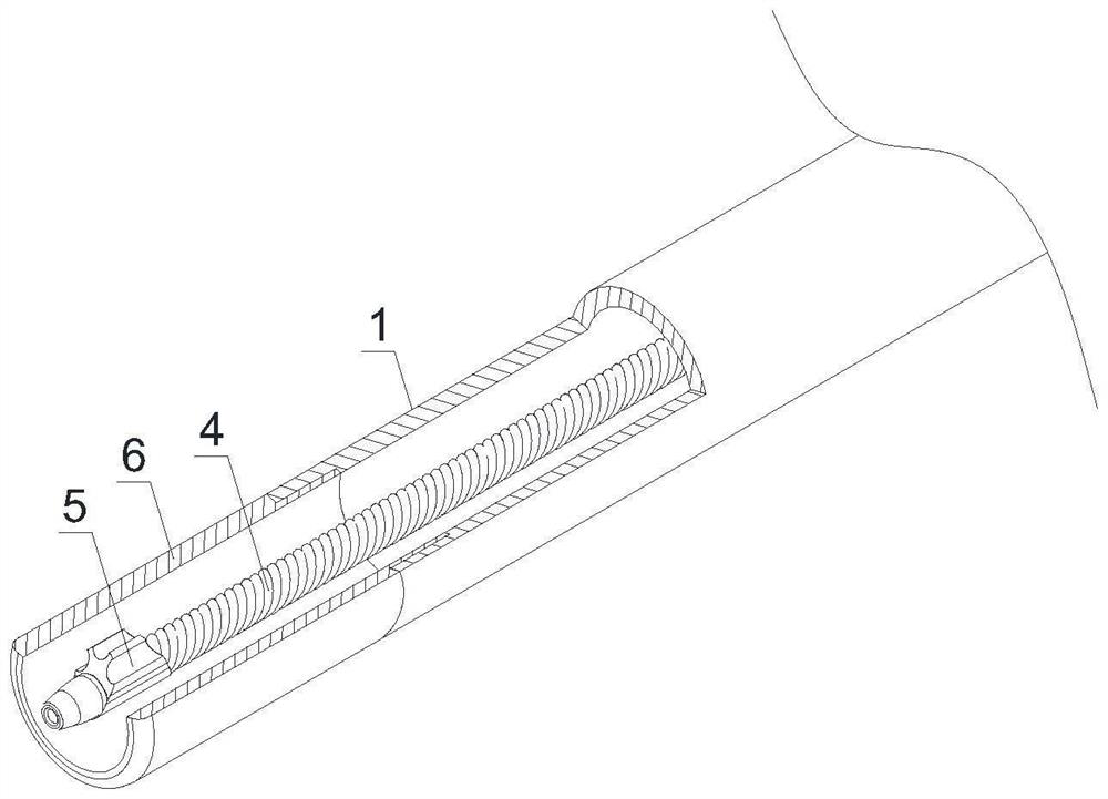
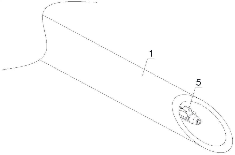
[0047] like Figure 1-Figure 22 As shown, an orbital mechanical thrombus suction catheter includes a suction catheter 1, and the proximal end of the suction catheter 1 is connected with a driving handle 3 through a three-way hemostasis valve 2, and a rotating mechanism is arranged inside the driving handle 3, and the suction catheter 1 is equipped with a transmission shaft 4 and an eccentric metal head 5;

[0048] like Figure 4 As shown, the distal end of the suction catheter 1 is provided with a metal connecting pipe 6;

[0049] like Figure 1-Figure 5 As shown, the proximal end of the transmission shaft 4 passes through the three-way hemostasis valve 2 and is connected to the rotating mechanism in the drive handle 3, and the distal end of the transmission shaft 4 is connected with an eccentric metal head 5, and the center of mass of the eccentric metal head 5 deviates from the rotation axis of the transmission shaft 4 , The eccentric metal head 5 is located in the metal ...

Embodiment 2

[0062] like Figure 16 , Figure 17 As shown, for the hollow transmission shaft 4 and the hollow eccentric metal head 5, the driving handle 3 is designed, and the rotating mechanism inside the driving handle 3 is composed of a motor 301, a driving gear 302, a driven gear 303, A hollow shaft 304 is formed. The motor 301 is connected with a drive gear 302 through a coupling 305. The drive gear 302 is movably installed in the drive handle 3 through a bearing. The driven gear 303 is fixed on the hollow shaft 304. The hollow shaft 304 is movably installed in the drive handle 3 through a bearing. In the driving handle 3 , the driving gear 302 meshes with the driven gear 303 , and the transmission shaft 4 is fixed on the far end of the hollow shaft 304 . The transmission shaft 4 is installed in the distal tube of the hollow shaft 304 with interference fit, and fixed by welding or glue. Other structures are the same as in Embodiment 1.

[0063] The motor 301 in the driving handle 3...


PUM


Abstract

The invention discloses a rail type mechanical thrombus suction catheter, and belongs to the technical field of vascular intervention medical instruments. The device comprises a suction catheter, wherein a transmission shaft and an eccentric metal head are arranged in the suction catheter; a metal connecting tube is arranged at the far end of the suction catheter; the far end of the transmission shaft is connected with an eccentric metal head, the mass center of the eccentric metal head deviates from the rotating axis of the transmission shaft, and the eccentric metal head is located in the metal connecting pipe. The suction catheter adopts the eccentric metal head structure, the eccentric metal head performs eccentric conical swing at the far end of the suction catheter, the suction area of the suction port can be increased through eccentric arrangement, the suction acting force of the suction port is improved, meanwhile, the eccentric conical swing crushing structure crushes large thrombus near the suction port, thrombus blockage near the suction port is reduced, and the suction effect is improved. The thrombus aspiration efficiency is improved, blood loss is reduced, and the operation time is shortened.

Description

technical field [0001] The invention relates to an orbital mechanical thrombus suction catheter, which belongs to the technical field of vascular interventional medical devices. Background technique [0002] Abnormal blood flow in blood vessels, such as blood turbulence, slow flow, etc., can lead to the formation of thrombus, blockage of blood vessels or narrowing of blood vessels, resulting in restricted blood supply in the downstream area of ​​the vascular system. This hemodynamic abnormality can cause a series of adverse consequences such as tissue hypoxia, abnormal intravascular pressure, increased cardiac load and heart failure. When the thrombus is located in the neurovascular system, it may cause stroke; when the thrombus is located in the deep venous system of the lower extremities, it may cause swelling or paralysis of the lower limbs; when the thrombus is located in the pulmonary vascular system, it may cause pulmonary embolism, resulting in death of the patient. ...

Claims


Application Information

Patent Timeline
Patent Type & Authority Applications(China)
IPC IPC(8): A61B17/22A61B17/3207
CPCA61B17/22A61B17/320758A61B2017/22038A61B2017/22079A61B2017/320741A61B2017/320766A61B2017/320775
Inventor 胡文忠刘晨旭李世文韩建超
Owner 上海融脉医疗科技有限公司
Learn More