Sample injection mode for digital micro-fluidic chip

A microfluidic chip and digital microfluidic technology, applied in laboratory containers, chemical instruments and methods, measuring tubes/pipettes, etc., can solve the problems of high cost, complex overall control, and difficult manufacturing, etc. Achieve the effect of reducing detection cost, improving detection efficiency, and reducing sample consumption

Inactive Publication Date: 2022-03-01
JIANGSU LOGILET BIOTECH CO LTD
View PDF6 Cites 2 Cited by
  • Summary
  • Abstract
  • Description
  • Claims
  • Application Information

AI Technical Summary

Problems solved by technology

Centrifugal force drive has high requirements for chip production. It is necessary to realize the function of the microvalve through a sudden change in the inner diameter, and it is necessary to ensure the air pressure balance of each channel during rotation. It is difficult to control the consistency of the chip.
Pneumatic drive type requires an external air source and multiple control valves, which requires extremely high sealing of the air circuit, and the overall control is complicated and costly
In summary, the existing automatic sample injection method is difficult to manufacture, the cost is high, and the sample injection process is complicated, which is not conducive to assembly
It is difficult to ensure the consistency of injection of each chip in mass production, which is not conducive to mass production

Method used


Image

  • Sample injection mode for digital micro-fluidic chip
  • Sample injection mode for digital micro-fluidic chip
  • Sample injection mode for digital micro-fluidic chip

Examples


Embodiment 1

[0026] Example 1: Construction of sample injection device for digital microfluidic chip

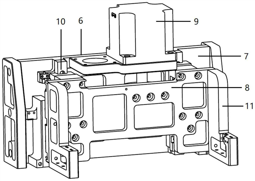
[0027] The sample injection device of the digital microfluidic chip mainly includes a sample injection pressure head 1 and a driving mechanism 6 for driving the movement of the sample injection pressure head. The sample injection head 1 is used for injecting the reagent pre-embedded in the chip 12 into the chip 12 . The driving mechanism 6 is used to control the movement of the sample injection pressure head 1 to realize automatic sample injection.

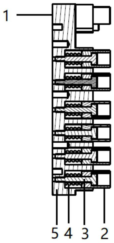
[0028] Figure 1-A with Figure 1-B The front view and cross-sectional view of the sample injection pressure head 1 are respectively shown. The sample injection pressure head 1 is composed of a plurality of pressure head bushings 2, plug screws 3, compression springs 4, and a sample injection pressure plate 5. The compression spring 4 is assembled between the sample injection pressure plate 5 and the pressure head bushing 2. There is a step...

Embodiment 2

[0037] Example 2: Sample injection method for digital microfluidic chip

[0038] Figure 5-A with Figure 5-B A front view and a cross-sectional view of the indenter bushing 2 fully injecting the reagent package in the microfluidic chip 12 into the chip are respectively shown. The movement of the driving motor 9 controls the movement of the injection pressure head 1. The pressure head sleeve 2 assembled in the injection pressure head 1 has an initial working position and a compression position when it is active. When the pressure head sleeve 2 is in the initial working position, it is driven by the drive motor. 9 Drive the sample injection pressure head 1 to move towards the reagent package sealed in the microfluidic chip until the pressure head sleeve 2 touches the reagent package and compresses the reagent package to cause it to break, and the reagent in the reagent package is injected into the chip. The compression spring 4 assembled by the pressure head shaft sleeve 2 pu...


PUM


Abstract

The invention discloses a sample injection method and device for a digital micro-fluidic chip. The sample injection device of the digital micro-fluidic chip mainly comprises a sample injection pressure head (1) and a driving mechanism (6) for driving the sample injection pressure head to move. And the sample injection pressure head (1) is used for injecting a reagent pre-embedded in the chip (12) into the chip (12). And the driving mechanism (6) is used for controlling the sample injection pressure head (1) to move so as to realize automatic sample injection. The sample injection mode has the advantages of high sensitivity, high accuracy, high flux, high integration level and the like, cross contamination is avoided in the whole process reaction, one-key operation can be achieved, and the two hands of an operator are greatly liberated.

Description

technical field [0001] The invention relates to a sample injection method and device for a digital microfluidic chip. Background technique [0002] At present, the digital microfluidic chip needs to be used in conjunction with a detection reagent to have a specific detection function. In the prior art, a pipette gun is usually used to draw a certain amount of liquid reagent sample and align it with the chip inlet. , inject the reagent into the chip completely. However, using a pipette gun to inject reagents increases the cost of use, the process is cumbersome, and has a strong dependence on it. Traditional sampling methods cannot realize the pre-embedding of detection reagents on digital microfluidic chips, which greatly limits The working environment and sampling conditions of the digital microfluidic chip. [0003] At present, the microfluidic chips that use automatic sample injection on the market are mostly driven by centrifugal force or air pressure. Centrifugal forc...

Claims


Application Information

Patent Timeline
Patent Type & Authority Applications(China)
IPC IPC(8): B01L3/00B01L3/02
CPCB01L3/0293B01L3/5027
Inventor 邓轲苏阳张研
Owner JIANGSU LOGILET BIOTECH CO LTD
Why Eureka
Try Eureka