
Quadruped robot driven by rotary rolling diaphragm and multi-gait driving method of quadruped robot

A quadruped robot and rolling diaphragm technology, which can be used in motor vehicles, transportation and packaging, etc., can solve the problems of reducing actuator efficiency and mechanical efficiency, and achieve the effects of improving driving efficiency, reducing friction loss, and making folding easier

Active Publication Date: 2022-03-01
HANGZHOU DIANZI UNIV
View PDF6 Cites 0 Cited by
  • Summary
  • Abstract
  • Description
  • Claims
  • Application Information

AI Technical Summary

Problems solved by technology

McKibben deforms through the outer braided mesh, which has large inelastic deformation, which reduces the efficiency of the actuator and introduces a nonlinear air pressure-tension relationship, and the mechanical efficiency is only 25%-49%.

Method used


Image

  • Quadruped robot driven by rotary rolling diaphragm and multi-gait driving method of quadruped robot
  • Quadruped robot driven by rotary rolling diaphragm and multi-gait driving method of quadruped robot
  • Quadruped robot driven by rotary rolling diaphragm and multi-gait driving method of quadruped robot

Examples


Embodiment 1

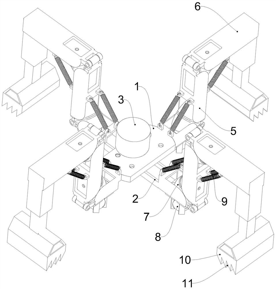
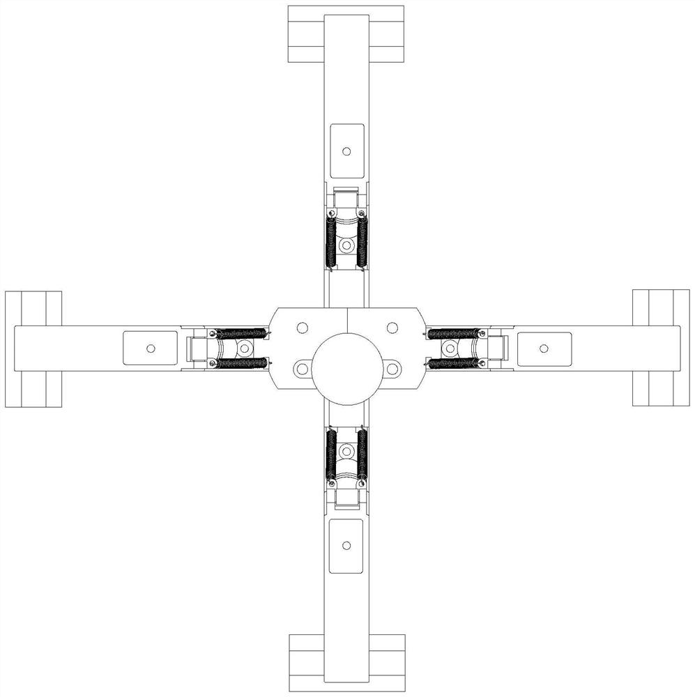
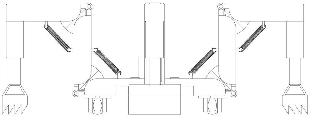
[0049] Such as figure 1 , 2 As shown in and 3, a quadruped robot driven by a rotating and rolling diaphragm includes a first chassis 1, a second chassis 2, a motor 3, a ball 8 and a driving foot assembly. Both the first chassis 1 and the second chassis 2 are elongated. The middle part of the first chassis 1 is rotatably connected with the middle part of the second chassis 2 . The second chassis 2 is located below the first chassis 1 . The middle part of the first chassis 1 is fixed to the casing of the motor 3 ; the main shaft of the motor 3 is fixedly connected to the second chassis 2 through a flange coupling 4 . Both ends of the bottom of the first chassis 1 and the second chassis 2 are equipped with balls 8 . The bottoms of the four balls 8 are flush.

[0050] The four driving foot assemblies are installed on the two ends of the first chassis 1 and the second chassis 2 respectively. The driving foot assembly includes a first bionic leg 5, a second bionic leg 6, a rot...

Embodiment 2

[0079] Such as Figure 7 As shown, a quadruped robot driven by a rotating and rolling membrane. The difference between this embodiment and Embodiment 1 is: between the inner side of the first bionic leg 5 and the first chassis 1, and between the first bionic leg 5 and the second No tension spring 9 is passed between the inner sides of the bionic legs 6 . The rotary rolling diaphragm driver 7 performs contraction reset through pressure control, specifically as follows:

[0080] The outer end surface of the second housing 7-2 of the rotary rolling diaphragm driver 7 is fixed with a sealing plate 7-8; the middle part of the sealing plate 7-8 is provided with a through hole 7-9; the arc connecting part 7-5 passes through the A hole 7-9; a sealing ring 7-10 is arranged between the through hole 7-9 and the arc-shaped connection part 7-5;

[0081] The piston body 7-4 divides the fan-shaped chamber in the casing into a first pressure chamber and a second pressure chamber; the first ...


PUM


Abstract

The invention discloses a quadruped robot driven by a rotary rolling diaphragm and a multi-gait driving method of the quadruped robot. The quadruped robot comprises two chassis and four driving foot assemblies. And the middle parts of the two chassis are rotationally connected and are driven by a power element to rotate relatively. The four driving foot assemblies are installed at the two ends of the two chassis correspondingly. The driving foot assembly comprises a first bionic leg, a second bionic leg and a rotary rolling diaphragm driver; the inner ends of the first bionic legs are rotationally connected to the end parts of the corresponding chassis; and the inner end of the second bionic leg is rotationally connected with the outer end of the first bionic leg. Rotary rolling diaphragm drivers are mounted on the inner side of the joint of the chassis and the first bionic leg and the inner side of the joint of the first bionic leg and the second bionic leg; the rotary rolling diaphragm driver is used for driving the first bionic leg and the second bionic leg to rotate. The rotary rolling diaphragm driver used in the invention has no obvious loss caused by viscoelastic deformation, coulomb friction, viscosity and external meshing.

Description

technical field [0001] The invention belongs to the technical field of soft robots, and in particular relates to a quadruped robot driven by a rotating and rolling diaphragm and a multi-gait driving method thereof. Background technique [0002] Fluid actuators are ubiquitous, and they can be installed as small drives on large excavators or on mobile robots. The compact and power-dense fluid drive principle, with light moving parts, allows power distribution and transmission from the central accumulator to the remote actuators. Piston-cylinder and telescoping fluid actuators output constant force under isobaric conditions. But external mechanisms are required to convert force and torque, resulting in inefficient losses and non-linear force characteristics. The vane actuator can directly output torque, and the piston-cylinder and vane actuator adopt press-fit seals, resulting in viscous and Coulomb friction. The mechanical efficiency of the piston-cylinder actuator can be a...

Claims


Application Information

Patent Timeline
Patent Type & Authority Applications(China)
IPC IPC(8): B62D57/032B62D57/02
CPCB62D57/032B62D57/022
Inventor 许明张帝
Owner HANGZHOU DIANZI UNIV
Learn More