Autoclaved aerated concrete slab

A concrete slab and autoclaved aerated technology, which is applied to building components, building insulation materials, thermal insulation, etc., can solve the problems of single autoclaved aerated concrete slab structure, lack of firmness, poor seismic effect, etc., and achieve improved Antifreeze effect, good pouring compactness, good high temperature resistance effect

Active Publication Date: 2022-03-01
YOUBO LUOKE NEW BUILDING MATERIALS (CHANGXING) CO LTD
View PDF7 Cites 0 Cited by
  • Summary
  • Abstract
  • Description
  • Claims
  • Application Information

AI Technical Summary

Problems solved by technology

[0003] The purpose of the present invention is to at least solve one of the technical problems in the prior art. The autoclaved aerated concrete slab of the present invention can solve the problem that the autoclaved aerated concrete slab is relatively simple in structure, and does not have high-strength firmness and shock resistance. Poor effect and other problems

Method used


Image

  • Autoclaved aerated concrete slab
  • Autoclaved aerated concrete slab
  • Autoclaved aerated concrete slab

Examples


Embodiment 1

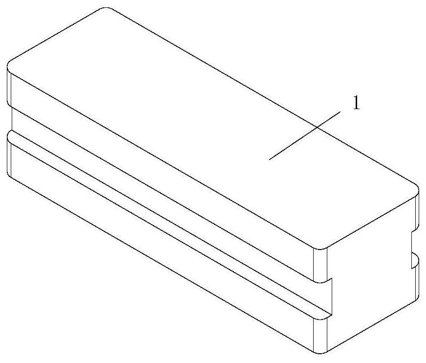
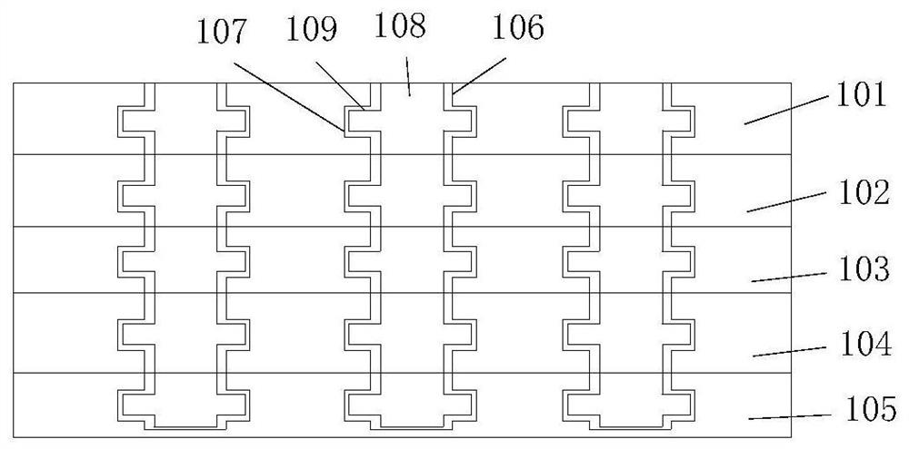
[0031] see Figure 1-2 , the present invention provides an autoclaved aerated concrete slab technical solution: an autoclaved aerated concrete slab, comprising a concrete slab 1, the concrete slab 1 is composed of an upper waterproof layer 101, an upper heat insulation layer 102, a sound insulation layer 103, a lower heat insulation layer 104 and The lower waterproof layer 105 is combined, the lower side of the upper waterproof layer 101 is poured with an upper heat insulation layer 102, the lower side of the upper heat insulation layer 102 is poured with a sound insulation layer 103, and the lower side of the sound insulation layer 103 is poured with a lower heat insulation layer 104 , the lower side of the lower heat insulation layer 104 is poured with a lower waterproof layer 105, which is formed by combining the concrete slab 1 with an upper waterproof layer 101, an upper heat insulation layer 102, a sound insulation layer 103, a lower heat insulation layer 104, and a lower...

Embodiment 2

[0034] see Figure 1-3On the basis of Embodiment 1, the upper side of the upper waterproof layer 101 is provided with a through groove 106 that penetrates the interior of the upper waterproof layer 101 and the upper heat insulation layer 102, the sound insulation layer 103, the lower heat insulation layer 104 and the lower waterproof layer 105. , the interior of the upper waterproof layer 101 is provided with an inner groove 107 communicating with the through groove 106, and the interior of the upper heat insulation layer 102, the sound insulation layer 103, the lower heat insulation layer 104 and the lower waterproof layer 105 is also provided with an inner groove 107. The inside of the groove 106 is poured with a through column 108, and the inside of the inner groove 107 is poured with a fixed column 109 with the same material as the through column 108. By utilizing the through groove 106 that is opened up and down in the interior of the concrete slab 1, the through column 10...

Embodiment 3

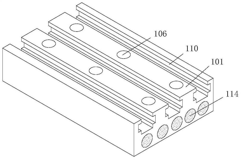
[0037] see Figure 4-5 On the basis of Embodiment 1, an upper groove 110 is provided on the upper side of the upper waterproof layer 101, and the left and right sides of the upper waterproof layer 101, the upper heat insulation layer 102, the sound insulation layer 103, the lower heat insulation layer 104 and the lower waterproof layer 105 The side is fixedly connected with the second rectangular plate 112 and the first rectangular plate 111, and the inner wall of the upper tank 110 is poured with an upper column 113 fixedly connected with the first rectangular plate 111 and the second rectangular plate 112, through the upper waterproof layer 101, the upper The first rectangular plate 111 and the second rectangular plate 112 of a rectangular surface are poured on both sides of the heat insulation layer 102, the sound insulation layer 103, the lower heat insulation layer 104 and the lower waterproof layer 105, which ensures the upper waterproof layer 101 and the upper heat insul...


PUM


Abstract

The invention discloses an autoclaved aerated concrete slab, and relates to the technical field of concrete planks, the autoclaved aerated concrete slab comprises a concrete slab, the concrete slab is formed by combining an upper waterproof layer, an upper heat insulation layer, a sound insulation layer, a lower heat insulation layer and a lower waterproof layer, the upper heat insulation layer is poured on the lower side of the upper waterproof layer, and the sound insulation layer is poured on the lower side of the upper heat insulation layer; a lower heat insulation layer is poured on the lower side of the sound insulation layer. According to the autoclaved aerated concrete slab, the first rectangular plate and the second rectangular plate with the protection function are fixedly arranged on the two sides of the upper waterproof layer, the upper heat insulation layer, the sound insulation layer, the lower heat insulation layer and the lower waterproof layer, so that the firmness and the high-temperature resistance of the autoclaved aerated concrete slab are improved; and meanwhile, the compressive strength, the corrosion resistance and the anti-seismic property of the autoclaved aerated concrete slab are greatly improved.

Description

technical field [0001] The invention relates to the technical field of concrete slabs, in particular to an autoclaved aerated concrete slab. Background technique [0002] The autoclaved aerated concrete slab is made of siliceous material and calcareous material as the main raw material, mixed with air-generating agent, stirred by adding water, forming pores by chemical reaction, and made through pouring molding, pre-oxygen cutting, autoclaved curing and other processes. Because most of the autoclaved aerated concrete slabs on the market are used after pouring and molding, it is easy to cause the structure of the autoclaved aerated concrete slab to be relatively simple, resulting in the failure of the autoclaved aerated concrete slab. The board does not have the problems of high-strength firmness and poor shock resistance. Contents of the invention [0003] The purpose of the present invention is to at least solve one of the technical problems in the prior art. The autocla...

Claims


Application Information

Patent Timeline
Patent Type & Authority Applications(China)
IPC IPC(8): E04C2/288E04C2/30E04C2/32E04B1/90E04B1/66E04B1/68
CPCE04C2/288E04C2/30E04C2/324E04B1/90E04B1/66E04B1/68E04B1/6806
Inventor 杨永泉杨哲峰沈晓鹤
Owner YOUBO LUOKE NEW BUILDING MATERIALS (CHANGXING) CO LTD
Why Eureka
Try Eureka