Chip decoupling capacitor position determination method, device and system

A technology for decoupling capacitors and determining methods, applied in electrical digital data processing, CAD circuit design, special data processing applications, etc., can solve the problem of low efficiency of decoupling capacitor position confirmation, achieve position optimization, and enhance EMC performance.

Pending Publication Date: 2022-03-01
SHENZHEN TCL NEW-TECH CO LTD
View PDF0 Cites 3 Cited by
  • Summary
  • Abstract
  • Description
  • Claims
  • Application Information

AI Technical Summary

Problems solved by technology

[0004] Based on this, it is necessary to provide a method for determining the position of the decoupling capacitor on the chip that can quickly confirm the allowable distance between the decoupling capacitor and the power supply pin of the chip for the problem of inefficiency in confirming the position of the decoupling capacitor at the power supply pin of the above-mentioned traditional chip. Devices and systems

Method used


Image

  • Chip decoupling capacitor position determination method, device and system
  • Chip decoupling capacitor position determination method, device and system
  • Chip decoupling capacitor position determination method, device and system

Examples


Embodiment Construction

[0043] In order to make the purpose, technical solution and advantages of the present application clearer, the present application will be further described in detail below in conjunction with the accompanying drawings and embodiments. It should be understood that the specific embodiments described here are only used to explain the present application, and are not intended to limit the present application.

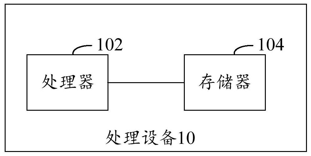
[0044]The method for determining the position of the chip decoupling capacitor provided by this application can be applied to such as figure 1 shown in the application environment. Wherein, the processing device 10 includes a processor 102 and a memory 104, and the processor 102 can be used to establish a first PCB three-dimensional model according to the chip to be tested and the PCB trace; the PCB trace is a trace connecting the power supply pin of the chip to be tested; According to the first PCB three-dimensional model and the decoupling capacitor set on the PCB trace...


PUM


Abstract

The invention relates to a chip decoupling capacitor position determination method, device and system. The method comprises the following steps: establishing a first PCB three-dimensional model according to a to-be-tested chip and PCB wiring; establishing a second PCB three-dimensional model according to the first PCB three-dimensional model and the decoupling capacitor, and confirming the position where the decoupling capacitor is arranged as the current position; acquiring a corresponding second S parameter according to a preset suction current frequency; inputting a preset EMI radiation excitation signal to the second PCB three-dimensional model, and outputting second EMI radiation intensity; if the second S parameter and the second EMI radiation intensity do not meet the preset EMI radiation condition, the decoupling capacitor is arranged on the PCB wiring between the power supply pin and the current position, the current position is updated to be the position where the decoupling capacitor is arranged until the preset EMI radiation condition is met, the updated current position is determined to be the optimized position of the decoupling capacitor, and the optimized position of the decoupling capacitor is determined to be the optimized position of the decoupling capacitor. The optimization of the position of the decoupling capacitor is realized, and the confirmation efficiency of the position of the decoupling capacitor is improved, so that the production efficiency of a chip circuit is improved.

Description

technical field [0001] The present application relates to the technical field of chip circuits, in particular to a method, device and system for determining the position of a chip decoupling capacitor. Background technique [0002] The high-frequency clock and high-speed signal of the chip need to draw current from the power supply pin of the chip during the high-low level switching process. The frequency of the current drawn is consistent with the frequency of the high-frequency clock and high-speed signal. The spectrum capabilities of these frequency signals on the PCB power supply traces cause EMI radiation to exceed the standard. It is usually necessary to provide a decoupling capacitor for the power supply pin of the chip to provide a smaller loop area for these spectral energies, reduce the size of the equivalent antenna for EMI radiation, and thereby reduce EMI radiation. Different locations of decoupling capacitors have different effects on EMI radiation intensity. ...

Claims


Application Information

Patent Timeline
Patent Type & Authority Applications(China)
IPC IPC(8): G06F30/392G06F115/12
CPCG06F30/392G06F2115/12
Inventor 余灿强陈欣刘国栋
Owner SHENZHEN TCL NEW-TECH CO LTD
Why Eureka
Try Eureka