Light source module

A light source module and light-emitting element technology, which is applied in the direction of electrical components, electric solid devices, circuits, etc., can solve problems such as halos, and achieve the effects of improving brightness, reducing assembly labor costs, and reducing overall thickness

Pending Publication Date: 2022-03-01
PRIMAX ELECTRONICS LTD
View PDF5 Cites 0 Cited by
  • Summary
  • Abstract
  • Description
  • Claims
  • Application Information

AI Technical Summary

Problems solved by technology

[0006] One of the objectives of the present invention is to provide a light source module, which uses the characteristics of powder materials of different colors, and mixes them into the polymer adhesive material in a specially prepared ratio to form a packaging adhesive material, and then fills the packaging adhesive material in the Above the LED die to solve the problem of halo

Method used


Image

  • Light source module
  • Light source module
  • Light source module

Examples


Embodiment Construction

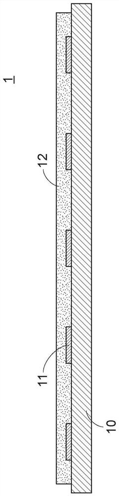
[0031] see figure 1 , which is a schematic cross-sectional view of a light source module according to an embodiment of the present invention. Such as figure 1 As shown, the light source module 1 of this embodiment includes a substrate 10 , a plurality of light emitting elements 11 disposed on the substrate 10 , and an encapsulant 12 . In this embodiment, the substrate 10 is, for example, a circuit board, and the light-emitting elements 11 are, for example, light-emitting diode chips, but the present invention is not limited thereto. Each light-emitting diode chip is electrically connected to the circuit board, so it can be Receives current from the circuit board and outputs light. The encapsulating adhesive material 12 is formed on the substrate 10, and the encapsulating adhesive material 12 covers the two light emitting elements 11. In this embodiment, the encapsulating adhesive material 12 includes a polymer adhesive material, a white powder material and a black powder mat...


PUM

PropertyMeasurementUnit
particle diameteraaaaaaaaaa

Abstract

The invention provides a light source module. The light source module comprises a substrate, a plurality of light-emitting elements and a packaging adhesive material, the light-emitting elements are arranged on the substrate. The packaging rubber material is configured on the substrate, and the packaging rubber material covers the light-emitting elements. The packaging adhesive material comprises a polymer adhesive material, a white powder material and a black powder material. The weight percentage of the polymer rubber material is 65%-99.8%, the weight percentage of the white powder material is 0.1%-20%, and the weight percentage of the black powder material is 0.1%-25%.

Description

technical field [0001] The invention relates to a light emitting module, in particular to a light source module with high luminous efficiency. Background technique [0002] The traditional manufacturing method of the light source module is to arrange multiple light-emitting diode dies in a matrix, and use surface-mount technology (Surface-mount technology, referred to as SMT) process to fix these light-emitting diode dies on the flexible circuit board (FPC) , Printed Circuit Board (PCB) or BT (Bismaleimide Triazine) resin substrate, and then fill in the required transparent encapsulant or fluorescent encapsulant. In addition, the method of encapsulating the adhesive material can also be used to fill the adhesive material above the LED die through a full-surface mold or potting compound, thereby achieving the purpose of protecting the LED die. [0003] No matter what kind of packaging method is used for the above light source module, the light-emitting diode grains are arran...

Claims


Application Information

Patent Timeline
Patent Type & Authority Applications(China)
IPC IPC(8): H01L33/56H01L25/075
CPCH01L33/56H01L25/0753H01L33/58
Inventor 杜雅琴郭宏玮
Owner PRIMAX ELECTRONICS LTD
Why Eureka
Try Eureka