
Automatic blow-off device and blow-off method suitable for guide pipes with various pipe diameters

A duct and pipe diameter technology, applied in the field of automatic duct blowing devices, can solve the problems of poor blowing effect, weakened blowing effect, low blowing efficiency, etc. Effect

Pending Publication Date: 2022-03-04
TIANJIN AEROSPACE CHANGZHENG ROCKET MFGCO
View PDF7 Cites 0 Cited by
  • Summary
  • Abstract
  • Description
  • Claims
  • Application Information

AI Technical Summary

Problems solved by technology

In actual operation, there are 10 different specifications for the diameter of the pipe to be blown from Φ6mm to Φ24mm. Due to the limitation of the pipe diameter, the existing equipment can only support the blowing of a single diameter pipe, usually using a specific clamp lock Manually open the valve to blow off after tightening the pipeline, or directly hold the pipeline to blow off
Regardless of whether the pipeline is fastened by a specific clamp or blown off by a person holding the pipeline, there are the following disadvantages: (1) The existing equipment is obviously restricted by the diameter of the pipeline
The specific fixture only supports the clamping of pipes of a single diameter, which cannot meet the simultaneous production of pipes of various diameters
(2) The blowing effect is poor, and there is no effective flexible port sealing method
Under the air source pressure of 1Mpa, whether it is clamping or hand-held pipeline blowing, pipe materials with different pipe diameters will have different sizes of air leakage at the port, which will weaken the blowing effect
(3) Lack of a reliable control mechanism for blowing off the pipeline
For different pipe diameters and different lengths, there are different implementation standards for blowing off time. The existing equipment relies on the initiative of the operator and cannot achieve standardization of production.
(4) Existing equipment only supports single blowing, the number of pipelines to be blown is large, and the actual blowing efficiency is low, often requiring 2-3 people to manually blow off to solve large-scale production tasks
[0003] This process is involved in the field of precision pipeline manufacturing, but due to the working conditions of many pipe diameters in aerospace systems, through industry understanding and patent inquiries, there are still technical gaps in the field of multi-diameter automatic blow-off, and there is no update at present. Effective pipe blowing device to replace existing process methods

Method used


Image

  • Automatic blow-off device and blow-off method suitable for guide pipes with various pipe diameters
  • Automatic blow-off device and blow-off method suitable for guide pipes with various pipe diameters
  • Automatic blow-off device and blow-off method suitable for guide pipes with various pipe diameters

Examples


Embodiment Construction

[0037] It should be noted that, in the case of no conflict, the embodiments of the present invention and the features in the embodiments can be combined with each other.

[0038] In describing the present invention, it should be understood that the terms "center", "longitudinal", "transverse", "upper", "lower", "front", "rear", "left", "right", " The orientations or positional relationships indicated by "vertical", "horizontal", "top", "bottom", "inner" and "outer" are based on the orientations or positional relationships shown in the drawings, and are only for the convenience of describing the present invention and Simplified descriptions, rather than indicating or implying that the device or element referred to must have a particular orientation, be constructed and operate in a particular orientation, and thus should not be construed as limiting the invention. In addition, the terms "first", "second", etc. are used for descriptive purposes only, and should not be understood ...


PUM


Abstract

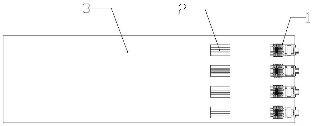
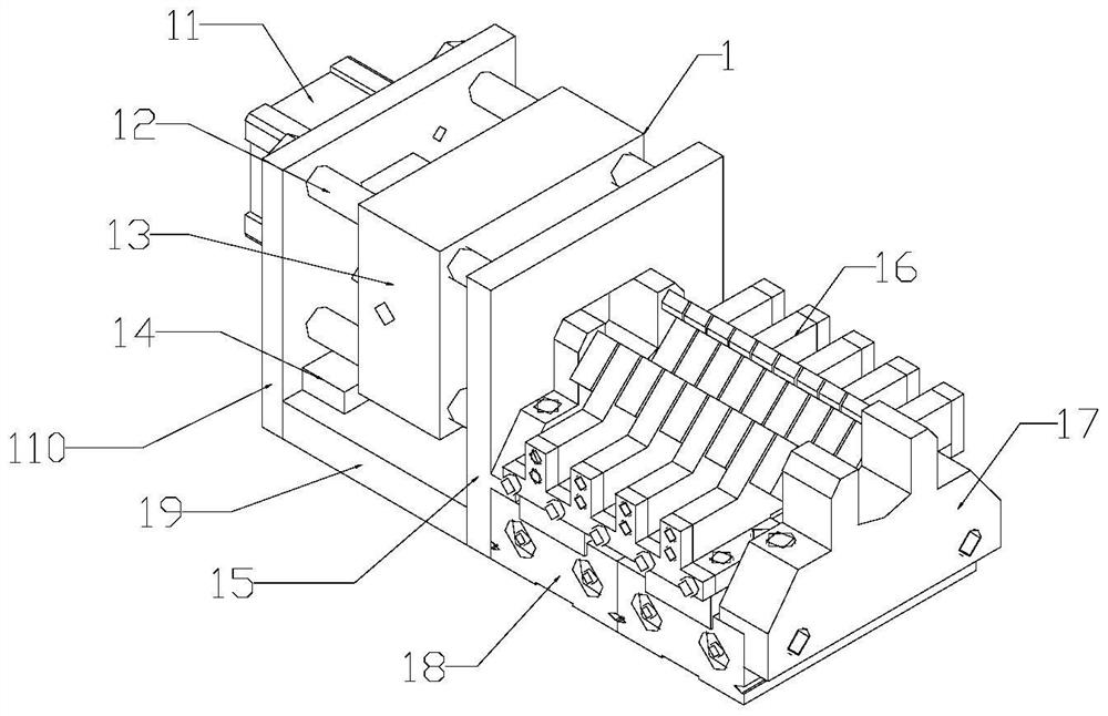
The invention provides an automatic conduit blow-off device and blow-off method.The automatic conduit blow-off device comprises a control unit, a plurality of pipeline brackets and a plurality of execution units, the pipeline brackets and the execution units are installed on an operation table top, the control unit is in signal connection with each execution unit, and each execution unit is matched with one pipeline bracket; the device is used for centering and clamping the guide pipe and blowing away objects in the guide pipe. According to the automatic blowing-off device and method suitable for the guide pipes with the various pipe diameters, the full-process operation of automatic centering clamping and low-pressure air blowing-off of the pipelines with the various pipe diameters can be achieved, the automatic blowing-off method of the pipelines is achieved in the control mode that automatic control serves as a main control mode and manual control serves as an auxiliary control mode, and manpower is liberated.

Description

technical field [0001] The invention belongs to the field of precision pipeline manufacturing, and in particular relates to an automatic blowing device and blowing method for pipes with various pipe diameters. Background technique [0002] Blowing of low-pressure gas pipelines is a key quality assurance method in the manufacturing process of aerospace pipelines. It is mainly used before pipeline bending or after pipeline pickling to ensure that there is no excess or residual moisture in the pipe diameter. In actual operation, there are 10 different specifications for the diameter of the pipe to be blown from Φ6mm to Φ24mm. Due to the limitation of the pipe diameter, the existing equipment can only support the blowing of a single diameter pipe, usually using a specific clamp lock After tightening the pipeline, manually open the valve to blow off, or directly hold the pipeline to blow off. No matter whether the pipeline is fastened by a specific clamp or blown off by a person...

Claims


Application Information

Patent Timeline
IPC IPC(8): B08B9/032B08B13/00
CPCB08B9/032B08B13/00
Inventor 张迪刘雪峰李曼张艳丰魏晶晶尚洪帅马康邹松华张杰杜鹏李斌王帅东徐松罗全冯晓路韩晨鹏杨中宝王卫鑫房浩弟李祖亮王晓双
Owner TIANJIN AEROSPACE CHANGZHENG ROCKET MFGCO
Learn More