General centrifugal fan capable of being rapidly arranged

A centrifugal fan, fast technology, applied in parts of pumping devices for elastic fluids, mechanical equipment, machines/engines, etc., to achieve the effects of shortening disassembly time, reducing processing costs, and reducing switching time

Pending Publication Date: 2022-03-04
华能重庆两江燃机发电有限责任公司
View PDF0 Cites 2 Cited by
  • Summary
  • Abstract
  • Description
  • Claims
  • Application Information

AI Technical Summary

Problems solved by technology

The power line and secondary line of the general centrifugal fan are mostly connected by bolts, and the disassembly time takes about 30min / (place · person)

Method used


Image

  • General centrifugal fan capable of being rapidly arranged
  • General centrifugal fan capable of being rapidly arranged
  • General centrifugal fan capable of being rapidly arranged

Examples


Embodiment Construction

[0021] The present invention will be described in further detail below by means of specific embodiments:

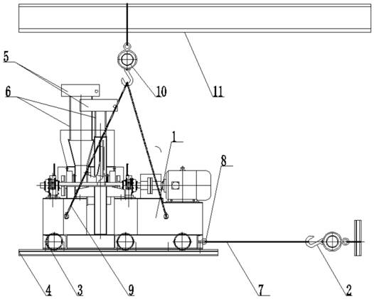
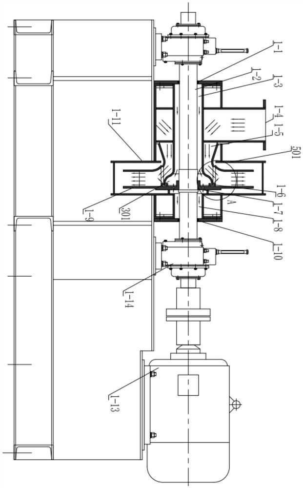
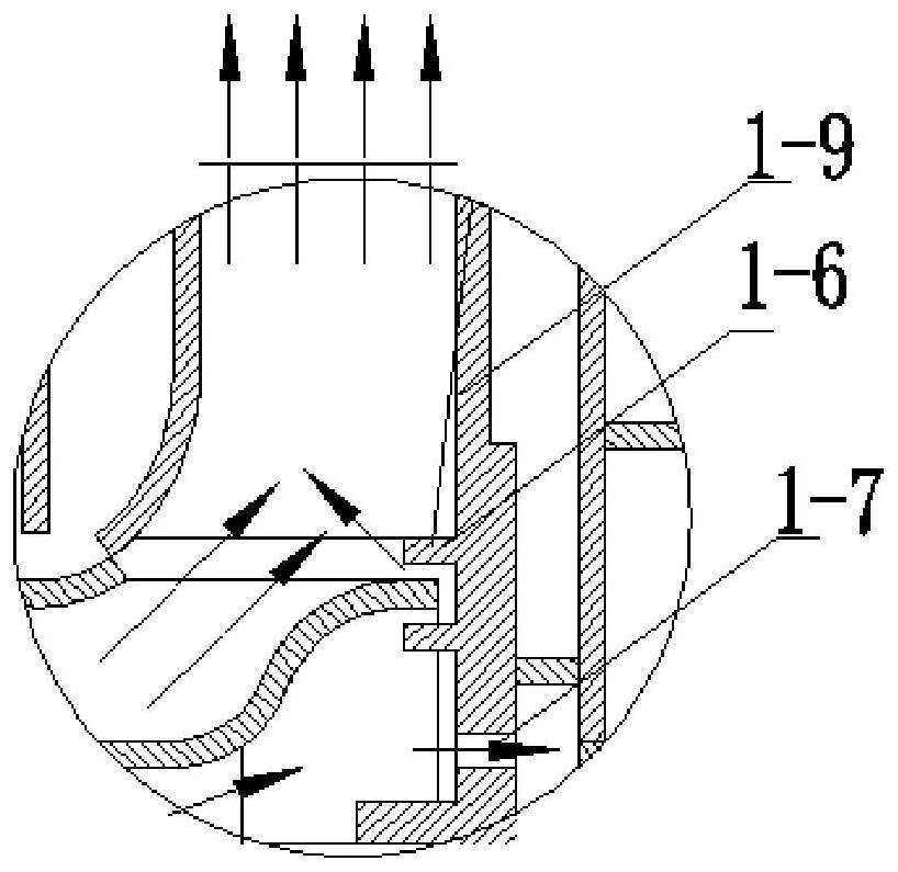
[0022] like Figure 1-3 As shown, the general-purpose centrifugal fan that can be quickly arranged includes a general-purpose centrifugal fan body 1. The general-purpose centrifugal fan body 1 is provided with an air inlet and an air outlet. It is characterized in that: the top of the general-purpose centrifugal fan body is equipped with a 1. The top hoisting machine 10 lifted off the ground. The body of the universal centrifugal fan is provided with connecting lugs for connecting with the hoisting rope 9 of the top hoisting machine. The hoisting rope 9 is connected to the top hoisting machine 10, and the top hoisting machine 10 is installed on the top On the hoisting mechanical beam 11. The front side of the general centrifugal fan body is provided with a pull hook 8, which is connected with a steel wire rope 7, and the steel wire rope 7 is connected with the cable hois...


PUM


Abstract

When the universal centrifugal fan capable of being rapidly arranged moves, a universal centrifugal fan body is hoisted away from the ground through a jack or a top hoisting machine, then a sliding rail is laid below the universal centrifugal fan body, and a pulley is connected to the sliding rail in a sliding mode; the universal centrifugal fan body is pulled to a designated installation position through the cable-stayed hoist; high-temperature-resistant connecting hoses are arranged on an air inlet and an air outlet of the universal centrifugal fan body, and hoops used for fixing the hoses to a system pipeline are arranged at the ends of the connecting hoses. The universal centrifugal fan capable of being rapidly arranged can be conveniently and rapidly moved to a proper position, an inlet and an outlet are connected through hoses and hoops, direct disassembly can be achieved, and the disassembly time is shortened.

Description

technical field [0001] The invention relates to the technical field of general centrifugal fans, in particular to a general centrifugal fan that can be arranged quickly. Background technique [0002] In recent years, with the increasingly stringent national environmental protection requirements, SCR out-of-stock ammonia injection systems have been widely used in thermal power units. The general-purpose centrifugal fan is an important equipment for hot air in the SCR denitrification system. During operation, the working environment is poor, and the working temperature is about 600°C. During the start-up and stop of the dilution fan, the fan shaft is often damaged due to excessive thermal deformation. Therefore, during the operation of the thermal power unit, the dilution fan will be disassembled and inspected within a certain period of time. Using traditional connection methods and unit movement methods often reduces the maintenance efficiency of equipment due to disassembly...

Claims


Application Information

Patent Timeline
Patent Type & Authority Applications(China)
IPC IPC(8): F04D29/00F04D29/42F04D29/62
CPCF04D29/002F04D29/4206F04D29/4213F04D29/626
Inventor 颜欣吴昌兵罗勇苏林潘剑林母德军姚飞许胜云汪华赵松李冠伯黄瑞丰陈云川孙亮刘宇
Owner 华能重庆两江燃机发电有限责任公司
Why Eureka
Try Eureka