

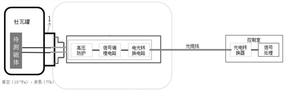
Electro-optical conversion device installed on flange face
An electro-optical conversion, flange surface technology, applied in the fields of magnetic performance measurement, superconducting performance measurement, etc., can solve the problems of increased difficulty in real quench signal extraction, high noise of quench detection signal, long transmission path, etc., and achieve rich functions. , to achieve the effect of small signal amplification and simple processing
- Summary
- Abstract
- Description
- Claims
- Application Information
AI Technical Summary
Problems solved by technology
Method used
Image

Examples
Embodiment Construction
[0042]The technical solutions in the embodiments of the present invention will be clearly and completely described below in conjunction with the accompanying drawings in the embodiments of the present invention. Obviously, the described embodiments are only part of the embodiments of the present invention, not all of them. Based on the embodiments of the present invention, all other embodiments obtained by persons of ordinary skill in the art without making creative efforts belong to the protection scope of the present invention.
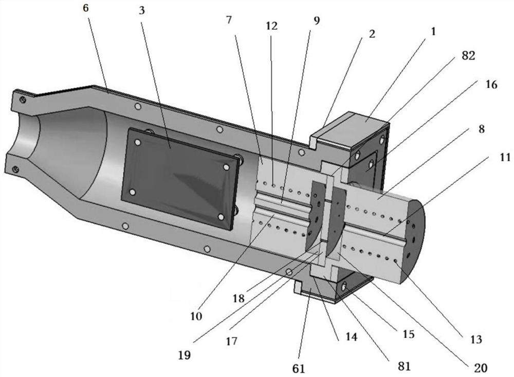
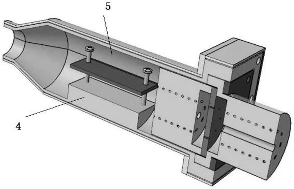
[0043] Such as Figure 1-4 As shown, an electro-optical conversion device installed on the flange surface of the present invention includes:
[0044] Flange 1 and flange cover plate 2, one end of the insulating shell 6 is connected to the flange 1, one end of the insulating shell 6 is a square end, the other end is a shrinking cylinder, and the middle is cylindrical, A platform is provided inside it for fixing the electro-optic conversion board 3, ...
PUM
 Abstract
Description
Claims
Application Information