
Real-time quantitative phase imaging method and system for label-free thick sample

A real-time quantitative and imaging system technology, applied in the measurement of phase influence characteristics, instruments, microscopes, etc., can solve the problems affecting real-time imaging capabilities, time-consuming, and inability to image, achieve excellent optical sectioning capabilities, simplify imaging methods, and simplify settings. Effect

Active Publication Date: 2022-03-04
HUAZHONG UNIV OF SCI & TECH
View PDF17 Cites 0 Cited by
  • Summary
  • Abstract
  • Description
  • Claims
  • Application Information

AI Technical Summary

Problems solved by technology

However, HD-GLIM needs to change the direction of sinusoidal grating projection on the basis of four-step phase shift. It needs 8 images to restore the two-dimensional phase, which is very time-consuming.
In addition, HD-GLIM is a transmission imaging optical path, which cannot image opaque samples
The asymmetric illumination of OBM leads to the inherent defect of anisotropy in its phase transfer function. To obtain isotropic imaging resolution by reconstructing the phase, illumination in multiple directions is required, which will affect the real-time imaging capability.

Method used


Image

  • Real-time quantitative phase imaging method and system for label-free thick sample
  • Real-time quantitative phase imaging method and system for label-free thick sample
  • Real-time quantitative phase imaging method and system for label-free thick sample

Examples


Embodiment Construction

[0030] In order to make the object, technical solution and advantages of the present invention clearer, the present invention will be further described in detail below in conjunction with the accompanying drawings and embodiments. It should be understood that the specific embodiments described here are only used to explain the present invention, not to limit the present invention. In addition, the technical features involved in the various embodiments of the present invention described below can be combined with each other as long as they do not constitute a conflict with each other.

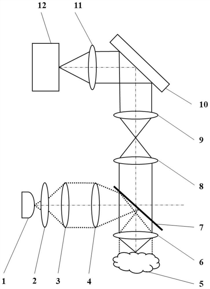
[0031] This method has excellent lateral resolution and optical sectioning capabilities due to the use of epi-illumination and partially coherent light sources. In epi-illumination, the objective lens is also used as a condenser lens for illumination, which ensures a high illumination numerical aperture and perfectly matches the numerical aperture of the objective lens, which can uniformly impro...


PUM

PropertyMeasurementUnit
heightaaaaaaaaaa

Abstract

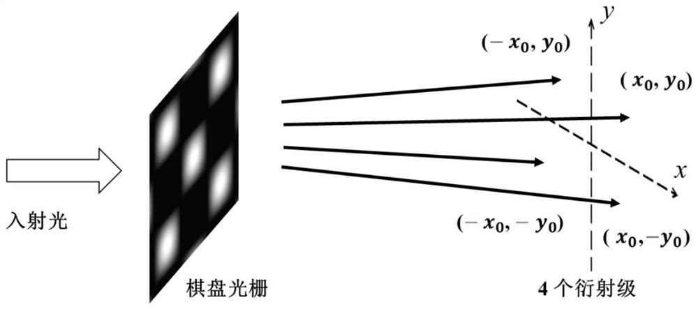
The invention provides a real-time quantitative phase imaging method and system for an unmarked thick sample. The method mainly comprises the following steps: collecting a light field reflected by a to-be-detected sample; performing diffracted light modulation on the light field; the amplitudes of the diffracted light in each period are approximately equal; acquiring an intensity pattern signal of a detection end and a target differential phase in a lateral shearing direction; performing phase shift processing of at least four different parameters of diffraction light modulation to obtain at least four intensity pattern signals; calculating according to the intensity pattern signal to obtain a differential phase sum in a lateral shearing direction; and performing Fourier transform on the differential phase sum to obtain a measurement phase in the lateral shearing direction. According to the imaging method and system, the resolution in the transverse shearing direction can be more uniform, the two-dimensional phase diagram can be obtained without changing the differential direction and the illumination direction, the structure is simple, and the calculation efficiency and the imaging speed can be remarkably improved by combining the imaging calculation method.

Description

technical field [0001] The invention relates to the field of phase imaging, in particular to a method and system for real-time quantitative phase imaging of unmarked thick samples. Background technique [0002] Quantitative phase imaging has great potential in the field of biomedicine, because it has the advantages of no labeling and no damage to the sample, and it has nanoscale phase sensitivity, diffraction-limited resolution, and large field of view. However, traditional quantitative phase imaging methods cannot image thick samples because multiple scattered light interferes with the sample information, and the light is absorbed by the sample, resulting in decreased contrast and limited imaging depth. [0003] In order to solve the problem in thick sample imaging, the phase gradient method of epi-type incoherent light illumination has become a new method. Currently, there are two classical phase gradient methods: oblique back-illumination imaging (OBM) and epi-emission g...

Claims


Application Information

Patent Timeline
Patent Type & Authority Applications(China)
IPC IPC(8): G02B21/06G02B21/12G02B27/50G01N21/41
CPCG02B21/06G02B21/12G02B27/50G01N21/41
Inventor 卢文龙王静怡
Owner HUAZHONG UNIV OF SCI & TECH
Learn More