Grouting device and grouting method for sleeve grouting

A sleeve grouting and sleeve technology, which is applied in the processing of building materials, structural elements, building components, etc., can solve problems such as holes in sleeve grouting, difficulty in ensuring grouting density, and inability to effectively remove air, so as to achieve construction efficiency High, shorten the construction time, avoid the effect of clogging

Active Publication Date: 2022-03-08
SOUTHEAST UNIV
View PDF20 Cites 4 Cited by
  • Summary
  • Abstract
  • Description
  • Claims
  • Application Information

AI Technical Summary

Problems solved by technology

[0003] However, the existing construction operation regulations are relatively general and less practical
In addition, the grouting pressure formed by the externally inserted grouting funnel is limited, and there is no effective grouting and air removal, resulting in holes in the sleeve grouting and potential quality problems
More importantly, the grouting technology is cumbersome, time-consuming and labor-intensive, and belongs to passive grouting technology, which has disadvantages such as low construction efficiency, difficulty in ensuring grouting density, many operators and long construction period.

Method used


Image

  • Grouting device and grouting method for sleeve grouting

Examples


Embodiment 1

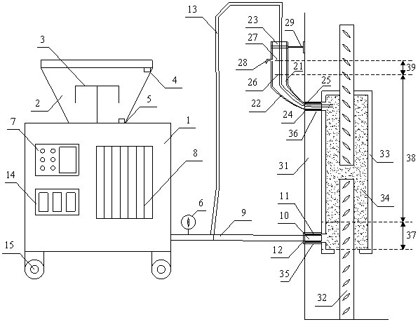
[0057] A grouting method for steel sleeve grouting is used for realizing high-efficiency grouting of the steel sleeve and ensuring the grouting quality.

[0058] (1) Pre-preparation: 1) Use an air compressor to remove dust, slag and other sundries inside steel bars and steel sleeves 33. If necessary, use clean water to wash away surface impurities, and use an air compressor to blow off excess water droplets; 2) Mix the grout mixture 34, the quality of the grout mixture 34 should meet the requirements of "Steel Sleeve Grout Mixture for Rebar Connection" (JG / T 408-2013), and it should be used within 30 minutes Finished; 3) Before connecting the grouting hole 35, carry out the test pumping to remove the air, water and other impurities in the grouting pipe 9, and remove the grouting material mixture 34 which is unevenly mixed, and wait for the mixing to be uniform and the color consistent The grouting material mixture 34 flows out for 2~3 s, and the grouting test is over; 4) Conne...

Embodiment 2

[0062] A grouting device and a grouting method for sleeve grouting, which are used to realize high-efficiency grouting of steel sleeves and ensure the quality of grouting.

[0063] In this embodiment, except for the grout filling pipe 13, the others are the same as in Embodiment 1.

[0064] If the grouting material mixture 34 on the booster pipe 21 drops below the suitable slurry line 26, the grout replenishment operation is performed, and the grout replenishment operation steps are as follows:

[0065] 1) Insert the grout filling pipe 13 from the booster pipe 21, and insert it into the steel sleeve 33 as deeply as possible;

[0066] 2) Keep the position of the grout feeding pipe 13 unchanged, feed grout at the first pressure until the mouth of the grout feeding pipe 13 is submerged by 5-20 mm, and the grout feeding speed is 3-5 mm / s;

[0067] 3) Keep the position of the grouting pipe unchanged, and use the pressure wave characterized by the second amplitude and the second fr...


PUM


Abstract

The invention discloses a grouting device and method for sleeve grouting. The grouting device comprises a grouting pump and a pressurizing pipe. The grouting pump comprises a grouting charging barrel, a controller, a fluctuation pressure pump and a grouting pipe; the controller is used for controlling the slurry pumping pressure of the fluctuation pressure pump during grouting, so that the fluctuation pressure pump generates waveform slurry pumping pressure with different amplitudes and / or different frequencies in at least three time periods in the grouting process; one end of the grouting pipe is connected with the fluctuation pressure pump, and the other end of the grouting pipe is connected with the grouting hole of the sleeve and used for conveying a grouting material mixture into the sleeve; the pressurizing pipe comprises a semi-rigid section, a rigid section and a supporting bracket. The method has the advantages of simple grouting operation, high construction efficiency and the like. The grouting material mixture moves up and down in the sleeve by fluctuating the slurry pumping pressure to generate vibration, so that the grouting material mixture is vibrated and bubbles are extruded, and the compactness of grouting is effectively ensured.

Description

technical field [0001] The invention relates to a construction technique for effectively ensuring the quality of sleeve grouting, belonging to the technical field of sleeve grouting, and in particular to a construction technique for effectively ensuring the compactness of sleeve grouting. Background technique [0002] The prefabricated reinforced concrete structure is conducive to the development of my country's construction industrialization, and is a modern construction industry characterized by "standardized production, factory production, assembly construction, finished product decoration, and information management". Compared with traditional cast-in-place structural buildings, it has: (1) it is beneficial to improve labor production efficiency and speed up the construction progress; (2) it is beneficial to ensure the quality of the project; (3) it is beneficial to reduce the cost of enterprises; (4) it is beneficial to energy saving Environmental protection and other...

Claims


Application Information

Patent Timeline
Patent Type & Authority Applications(China)
IPC IPC(8): E04G21/02E04C5/16
CPCE04G21/02E04C5/162E04C5/165
Inventor 汪昕刘长源吴智深朱中国
Owner SOUTHEAST UNIV
Why Eureka
Try Eureka