Plastic liner drying tank

A drying tank and liner technology, which is applied in drying, dryers, dryers for static materials, etc., can solve the problems of uneven heating, difficult processing and installation, and complicated working environment, so as to achieve easy disassembly and assembly. Effects of maintenance, improvement of corrosion resistance, and reduction of manufacturing costs

Inactive Publication Date: 2022-03-08
苏州普伊特自动化系统有限公司
View PDF6 Cites 0 Cited by
  • Summary
  • Abstract
  • Description
  • Claims
  • Application Information

AI Technical Summary

Problems solved by technology

The liners of the existing drying tanks used for drying silicon wafers in the industry are all made of metal and sprayed. The manufacturing cost is high, and it is not easy to process and install. The internal working environment of the tank is relatively complicated. Most of them work in acid, alkali, high temperature and humid environments, and are prone to rust during long-term use, greatly reducing their service life, resulting in unstable working conditions
[0003] In addition, the hot circulating air in the tank of the existing drying tank cannot be evenly distributed inside the tank, resulting in low drying efficiency; moreover, the old heating unit is installed in the tank, and the heating rod itself is expensive, and it is not heated in the tank. Uniformity is easy to cause damage, and the hot air blown out is unevenly distributed, resulting in poor subsequent processes, etc., and the cost of later maintenance and replacement is high, and it is not easy to disassemble and replace

Method used


Image

  • Plastic liner drying tank
  • Plastic liner drying tank
  • Plastic liner drying tank

Examples


Embodiment 1

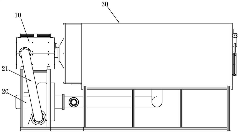
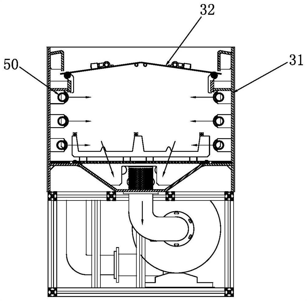
[0027] refer to Figure 1-3 The plastic liner drying tank provided by the present embodiment 1 includes a support frame 40 made of PVDF profiles, and the upper side of the support frame 40 is horizontally arranged with interconnected heating boxes 10 and tanks 30. On the support frame 40, there are also The fan 20 positioned at the outside of the heating box 10 and the tank body 30 is installed, the air inlet of the fan 20 is connected to the air outlet at the bottom of the tank body 30 through the air duct 21, and the air outlet of the fan 20 is connected to the inlet of the heating box 10 through the air duct 21. Tuyere; the inner wall of the tank body 30 is provided with a PVDF material liner 31 , and the upper side of the tank body 30 is provided with an openable cover plate 32 .

[0028] In this embodiment 1, the liner 31 inside the tank body 30 is designed and processed by PVDF material, and the support frame 40 is made of PVDF profiles. The mechanical properties of the...

Embodiment 2

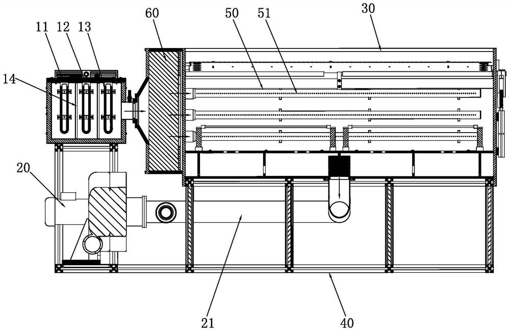
[0030] Based on Example 1, refer to figure 2 , 4 And 5, in the present embodiment 2, heating box 10 comprises box body 11, and the side wall of box body 11 is provided with air outlet; Box body 11 inside is vertically provided with two dividing plates 14 and the interior space of box body 11 is separated by S-shaped connected three-stage heating area, and the three-stage heating area is close to the tank body 30 from outside to inside, the air inlet of the heating box 10 is set on the side wall of the outermost heating area, and the air outlet on the side wall of the box body 11 is set on The side wall of the innermost heating area is also connected to the tank body 30; the inside of the box body 11 is also equipped with heating components respectively located in the three-stage heating area; the box body 11 is a hollow interlayer structure, and the hollow interlayer of the box body 11 is filled with Heat insulation cotton, heat insulation cotton makes the external heat radi...

Embodiment 3

[0033] Based on Example 2, refer to Figure 2-3 , in this embodiment 3, the inner side of the tank body 30 is also symmetrically provided with a hot air nozzle 50 located inside the liner 31 and three hot air nozzles 50 are arranged in parallel up and down on each side, and the air inlet of the hot air nozzle 50 is connected to the box body 11 The air outlet, and the side wall of each hot air nozzle 50 is provided with at least one row of air outlet holes 51 aligned with the heating space inside the box body 11 .

[0034] In this embodiment 3, the original blower 20 is changed to the current hot air nozzle 50 to blow air to form an air curtain, and three hot air nozzles 50 are arranged symmetrically on both sides to blow air evenly so that the hot air circulation inside the tank body 30 is distributed. More uniform, the heating of silicon wafers and other products is more uniform, and the drying efficiency is higher, thereby improving the production capacity of the equipment. ...


PUM


Abstract

The invention discloses a plastic inner container drying groove which comprises a supporting frame made of PVDF profiles, a heating box and a groove body which are communicated with each other are horizontally arranged on the upper side of the supporting frame side by side, a fan located outside the heating box and the groove body is further installed on the supporting frame, and an air inlet of the fan is communicated to an air outlet of the groove body through an air pipe. An air outlet of the fan is communicated to an air inlet of the heating box through an air pipe; an inner container made of PVDF materials is arranged on the inner wall of the tank body, and a cover plate capable of being opened and closed is arranged on the upper side of the tank body. The supporting frame and the inner container of the tank body are both made of PVDF materials, so that the manufacturing cost and the corrosion resistance of the drying tank are effectively reduced; the space in the tank body is effectively released by the independent external heating box; after the fan is externally arranged, a large-air-volume fan can be used for increasing the air speed so as to realize rapid temperature rise and stable working temperature.

Description

technical field [0001] The invention relates to the technical field of mechanical equipment, in particular to a plastic liner drying tank. Background technique [0002] Many products need to use drying equipment for drying in the production and processing process, especially with the rapid development of the solar energy industry, efficient drying of silicon wafers is one of the important processes in the preparation process of silicon wafers for solar cells. The liners of the existing drying tanks used for drying silicon wafers in the industry are all made of metal and sprayed. The manufacturing cost is high, and it is not easy to process and install. The internal working environment of the tank is relatively complicated. Most of them work in acid, alkali, high temperature and humid environments, and are prone to rust during long-term use, greatly reducing their service life and resulting in unstable working conditions. [0003] In addition, the hot circulating air in the ...

Claims


Application Information

Patent Timeline
Patent Type & Authority Applications(China)
IPC IPC(8): F26B9/06F26B21/00F26B21/04F26B25/08
CPCF26B9/066F26B21/001F26B21/003F26B21/004F26B21/04F26B25/08
Inventor 张淋王亚李安东
Owner 苏州普伊特自动化系统有限公司
Why Eureka
Try Eureka